Quick Intro
The next network service in our DC will be the tenant-based Inter-VNI, aka L3VNI.
L3VNI (Layer 3 Virtual Network Identifier) represents a VXLAN segment
used to enable routed (inter-subnet) communication between tenants or VRFs across the fabric, typically associated with a tenant VRF in the control plane.
Before configuring EVPN level of L3VNI, tenant VRF should be added to the appropriate switches. In the configuration snippet below I’ve added vrf DB and just like for the L2VNI allow switch to pick rd and route-target automatically.
vrf context DB
  vni 9003911
  rd auto
  address-family ipv4 unicast
    route-target both auto
    route-target both auto evpn
dc01-r01-leaf01# show vrf DB
VRF-Name VRF-ID State Reason
DB 3 Up -- The next step is to define routing interface for the Inter-VNI routing, this interface doesn’t have any IP address, since it is not advertised to any routing protocol, however it should be present on each switch participating in the routing for the particular VPN. When locally connected host initiates the traffic towards different subnet within the same VRF, this interface will receive the packet and forward it with added VNI information
vlan 3911
  name L3FORWARD
  vn-segment 9003911
!
interface Vlan3911
  no shutdown
  mtu 9216
  vrf member DB
  no ip redirects
  ip forward
  no ipv6 redirects
The last step required to be complete before we start routing the traffic between VNIs is to associate configured VLAN with NVE interface
interface nve1
  no shutdown
  host-reachability protocol bgp
  advertise virtual-rmac
  source-interface loopback0
  member vni 900100
    ingress-replication protocol bgp
  member vni 9003911 associate-vrf
L3 Network configuration
Now it is time to add a default gateway (SVI) for our previously configured VLAN100 and ensure that all previously enabled are working as expected
interface Vlan100
  no shutdown
  vrf member DB
  no ip redirects
  ip address 10.10.100.254/24
  no ipv6 redirects
  fabric forwarding mode anycast-gateway
Verification
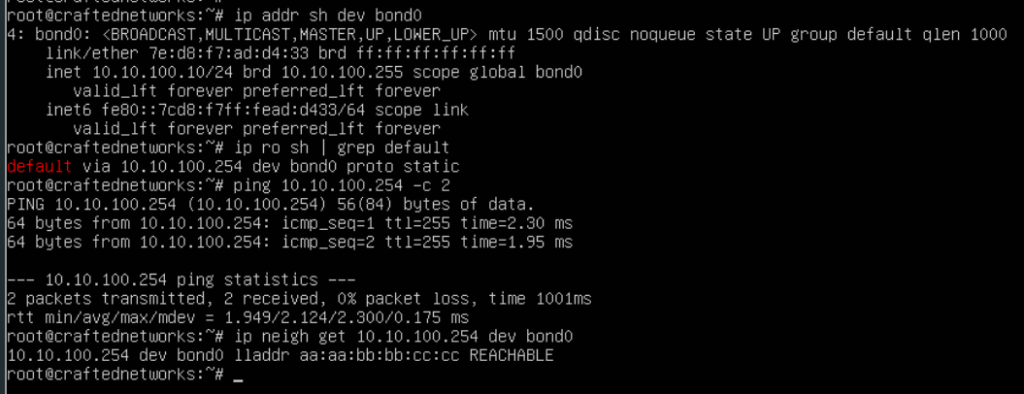
I’ll post few outputs from hosts connected to R01 and R02 switches, and what they see from their perspective.
First output shows that server connected with port-channel can reach its default gateway configured as an L3 interface on the leaf switch. Interesting part here is the ARP record pointing to our Anycast Gateway MAC we have configured during previous steps.
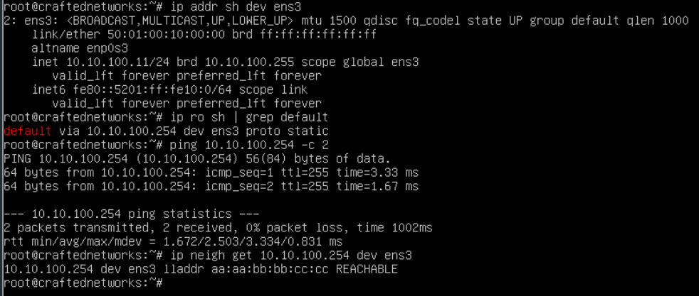
The second output shows pretty much the same information even though it is connected with a single interface to a separate VPC domain configured as a different pair of leaf switches.
In the next step I’ll add another VLAN and will show the communication process between these two VLANs.

Leave a comment