Quick Intro
In the last post I’ve configured SVI interface (AGW) attached to a VRF (tenant) and demonstrated that both servers connect to rack01 and rack02 switches can reach their default gateways and see the same MAC address associated with default gateway IP address.
This time we’ll add another VLAN to the same tenant and will demonstrate Inter-VNI connectivity.
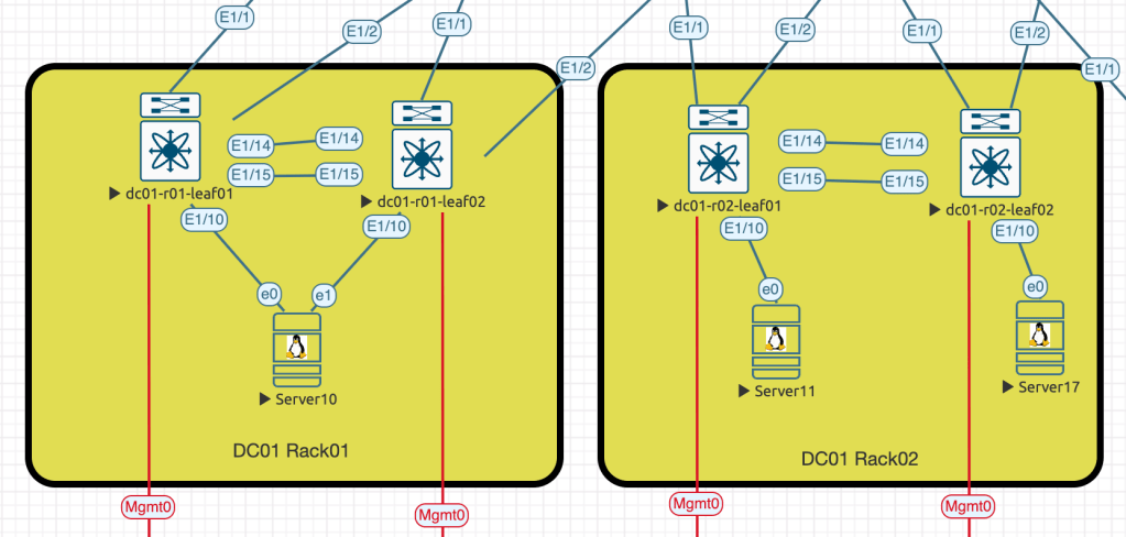
Server10 (10.10.100.10/24) and Server11(10.10.100.11/24) are part of the VLAN100
Server17 (10.10.101.17/24) is part of the VLAN101
Configuration
As a prerequisites we already have L3 forward interface configured (VLAN3911) to handle Inter-VNI traffic. All switches from the screenshot above have the following configuration applied:
vlan 3911
  name L3FORWARD
  vn-segment 9003911

vrf context DB
  vni 9003911
  rd auto
  address-family ipv4 unicast
    route-target both auto
    route-target both auto evpn

interface Vlan3911
  no shutdown
  mtu 9216
  vrf member DB
  no ip redirects
  ip forward
  no ipv6 redirects

interface nve1
  member vni 9003911 associate-vrf
Since Server17 attached to DC01 Rack02 (dc01-r02-leaf02) we need to provision VLAN101 to this pair of switches only. So the configuration below needs to be applied to both leaf switches within DC01 Rack02:
vlan 101
  name server-domain101
  vn-segment 900101

interface Vlan101
  no shutdown
  vrf member DB
  no ip redirects
  ip address 10.10.101.254/24
  no ipv6 redirects
  fabric forwarding mode anycast-gateway

interface nve1
  member vni 900101
    ingress-replication protocol bgp
And of course make sure the server port and server itself have proper configuration applied.
This settings will provide us connectivity between Server17 and SVI101, Server17 and Server11 connected to the same pair of switches, however, Server10 connected to DC01 Rack01 switches will still not be reachable for Server17.
DC01 Rack01 switches know nothing about VLAN101 configured on DC01 Rack02 switches. Here is how the routing dc01-r01-leaf01 switch routing and BGP table looks:
dc01-r01-leaf01# sho ip route vrf DB
IP Route Table for VRF "DB"
'*' denotes best ucast next-hop
'**' denotes best mcast next-hop
'[x/y]' denotes [preference/metric]
'%<string>' in via output denotes VRF <string>

10.10.100.0/24, ubest/mbest: 1/0, attached
    *via 10.10.100.254, Vlan100, [0/0], 2d18h, direct
10.10.100.10/32, ubest/mbest: 1/0, attached
    *via 10.10.100.10, Vlan100, [190/0], 2d18h, hmm
10.10.100.11/32, ubest/mbest: 1/0
    *via 10.255.255.102%default, [200/0], 09:13:33, bgp-65000, internal, tag 650
00, segid: 9003911 tunnelid: 0xaffff66 encap: VXLAN

10.10.100.254/32, ubest/mbest: 1/0, attached
    *via 10.10.100.254, Vlan100, [0/0], 2d18h, local

dc01-r01-leaf01# show nve vni
Codes: CP - Control Plane        DP - Data Plane
       UC - Unconfigured         SA - Suppress ARP
       SU - Suppress Unknown Unicast
       Xconn - Crossconnect
       MS-IR - Multisite Ingress Replication

Interface VNI      Multicast-group   State Mode Type [BD/VRF]      Flags
--------- -------- ----------------- ----- ---- ------------------ -----
nve1      900100   UnicastBGP        Up    CP   L2 [100]
nve1      9003911  n/a               Up    CP   L3 [DB]

BGP routing table information for VRF default, address family L2VPN EVPN
BGP table version is 2469, Local Router ID is 10.255.255.3
Status: s-suppressed, x-deleted, S-stale, d-dampened, h-history, *-valid, >-best
Path type: i-internal, e-external, c-confed, l-local, a-aggregate, r-redist, I-i
njected
Origin codes: i - IGP, e - EGP, ? - incomplete, | - multipath, & - backup, 2 - b
est2

   Network            Next Hop            Metric     LocPrf     Weight Path
Route Distinguisher: 10.255.255.3:3    (L3VNI 9003911)
*>l[2]:[0]:[0]:[48]:[5003.0000.1b08]:[0]:[0.0.0.0]/216
                      10.255.255.101                    100      32768 i
*>i[2]:[0]:[0]:[48]:[5005.0000.1b08]:[0]:[0.0.0.0]/216
                      10.255.255.102                    100          0 i
*>i[2]:[0]:[0]:[48]:[5006.0000.1b08]:[0]:[0.0.0.0]/216
                      10.255.255.102                    100          0 i
*>i[2]:[0]:[0]:[48]:[5001.0010.0000]:[32]:[10.10.100.11]/272
                      10.255.255.102                    100          0 i
* i                   10.255.255.102                    100          0 i
We need to force these switches learn information about VLAN101 by configuring “network” settings in a proper section of the BGP configuration:
router bgp 65000
  vrf DB
    address-family ipv4 unicast
      network 10.10.101.0/24
Verification
After “network 10.10.101.0/24” was added to both DC01 R02 switches the routing table on R01 switches changed accordingly:
dc01-r01-leaf01# sho ip route vrf DB
IP Route Table for VRF "DB"
'*' denotes best ucast next-hop
'**' denotes best mcast next-hop
'[x/y]' denotes [preference/metric]
'%<string>' in via output denotes VRF <string>
10.10.100.0/24, ubest/mbest: 1/0, attached
*via 10.10.100.254, Vlan100, [0/0], 2d18h, direct
10.10.100.10/32, ubest/mbest: 1/0, attached
*via 10.10.100.10, Vlan100, [190/0], 2d18h, hmm
10.10.100.11/32, ubest/mbest: 1/0
*via 10.255.255.102%default, [200/0], 09:37:12, bgp-65000, internal, tag 650
00, segid: 9003911 tunnelid: 0xaffff66 encap: VXLAN
10.10.100.254/32, ubest/mbest: 1/0, attached
*via 10.10.100.254, Vlan100, [0/0], 2d18h, local
10.10.101.0/24, ubest/mbest: 2/0
*via 10.255.255.5%default, [200/0], 00:07:15, bgp-65000, internal, tag 65000
, segid: 9003911 tunnelid: 0xaffff05 encap: VXLAN
*via 10.255.255.6%default, [200/0], 00:07:47, bgp-65000, internal, tag 65000
, segid: 9003911 tunnelid: 0xaffff06 encap: VXLAN
dc01-r01-leaf01# show bgp l2 evpn vni-id 9003911
BGP routing table information for VRF default, address family L2VPN EVPN
BGP table version is 2489, Local Router ID is 10.255.255.3
Status: s-suppressed, x-deleted, S-stale, d-dampened, h-history, *-valid, >-best
Path type: i-internal, e-external, c-confed, l-local, a-aggregate, r-redist, I-i
njected
Origin codes: i - IGP, e - EGP, ? - incomplete, | - multipath, & - backup, 2 - b
est2
Network Next Hop Metric LocPrf Weight Path
Route Distinguisher: 10.255.255.3:3 (L3VNI 9003911)
*>l[2]:[0]:[0]:[48]:[5003.0000.1b08]:[0]:[0.0.0.0]/216
10.255.255.101 100 32768 i
*>i[2]:[0]:[0]:[48]:[5005.0000.1b08]:[0]:[0.0.0.0]/216
10.255.255.102 100 0 i
*>i[2]:[0]:[0]:[48]:[5006.0000.1b08]:[0]:[0.0.0.0]/216
10.255.255.102 100 0 i
*>i[2]:[0]:[0]:[48]:[5001.0010.0000]:[32]:[10.10.100.11]/272
10.255.255.102 100 0 i
* i 10.255.255.102 100 0 i
*>i[5]:[0]:[0]:[24]:[10.10.101.0]/224
10.255.255.5 100 0 i
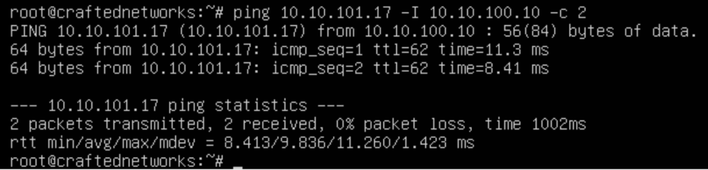
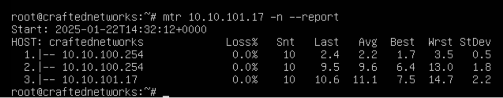
*|i 10.255.255.6 100 0 iAs a final verification step we’ll run ping and traceroute checks between Server10 and Server17
In the next steps I’ll review detailed step describing L2 and L3 communication process from the control-plane and data-plane perspective.

Leave a comment