In this post I’ll walk through the path of the packet for the bridged traffic (L2VNI). It is within the EVPN VXLAN network we configured earlier. We’ll try to cover each step and include related packet captures.
We’ll be using the same network as we used before, and we’ll be reviewing the connectivity between Server10 (10.10.100.10) and Server11 (10.10.100.11).
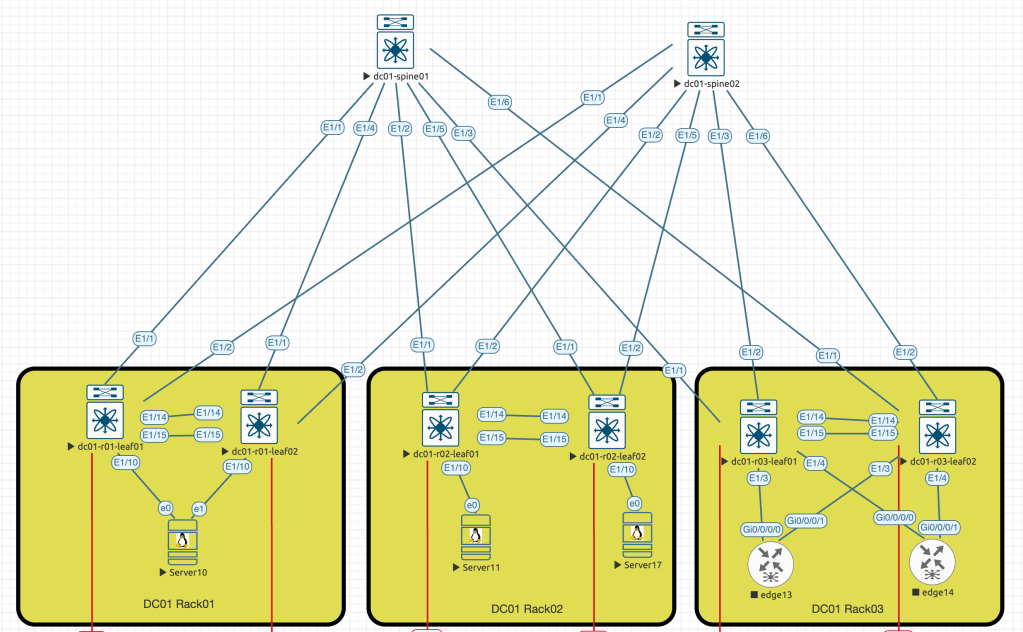
To simplify the packet capture process, I’ll shutdown second link between Server10 and dc01-r01-leaf02 switch (e1 <==> E1/10).
- ARP request from Server10 to Server11
In this step, I intentionally cleared the ARP cache on the Server10. This action was taken to force the server to send an ARP request towards the connected switch.
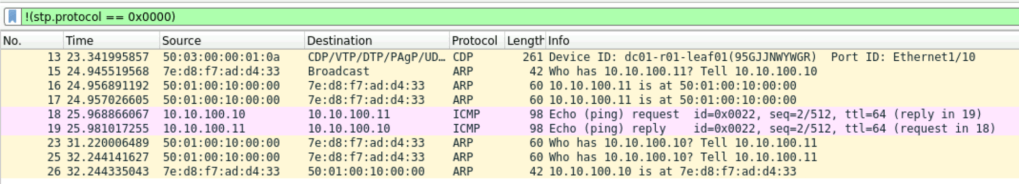
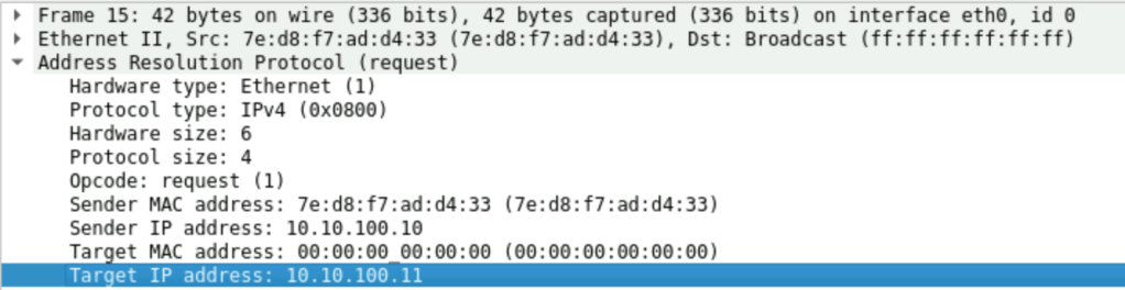
Frame #15 is an expected broadcast request sent by the Server10 to get the mac address information of Server11
We also can see that in the Frame #17 we received a reply from MAC: 50:01:00:10:00:00, which is our dc01-r01-leaf01 switch.
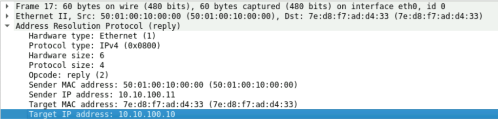
When a packet reaches the leaf switch, it will first check the ARP suppression cache. The leaf switch will then reply on behalf of the remote server. Initial broadcast frame will never be flooded to the network, due to configured suppress-arp feature. In the output below we also can note the remote vtep ip – 10.255.255.102, which is our leaf switch on the other end – dc01-r02-leaf01.
dc01-r01-leaf01# show ip arp suppression-cache detail

Flags: + - Adjacencies synced via CFSoE
       L - Local Adjacency
       R - Remote Adjacency
       L2 - Learnt over L2 interface
       PS - Added via L2RIB, Peer Sync
       RO - Dervied from L2RIB Peer Sync Entry

Ip Address      Age      Mac Address    Vlan Physical-ifindex    Flags    Remote Vtep Addrs

10.10.100.10    00:01:54 7ed8.f7ad.d433  100 port-channel10      L
10.10.100.11    00:01:54 5001.0010.0000  100 (null)              R        10.255.255.102
At this moment of time Server10 knows the mac address of the Server11 and ready to generate ICMP request.

2. ICMP request from Server10 to Server11
At the next stage Server10 is generating the ICMP packet with the destination IP and MAC address towards connected leaf.
To simplify the traffic capture I suspended few link to make the path between Server10 and Server11 more predictable, so we expected that packet will use the following route (use initial diagram as a reference):
Server10 -> (e1/10) dc01-r01-leaf01 -> (e1/1) dc01-spine01 -> (e1/1) dc01-r02-leaf02 -> (e0) Server11
We’ll capture the ICMP packet on the each interface within path shown above.
First stop is interface e1/10 on dc01-r01-leaf01, the interesting part here that DST MAC used in the frame, we’ll check the CLI output to see how leaf switch sees the destination:
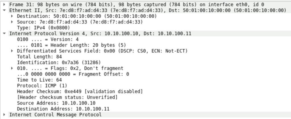
dc01-r01-leaf01# show mac address-table dynamic vlan 100
Legend:
* - primary entry, G - Gateway MAC, (R) - Routed MAC, O - Overlay MAC
age - seconds since last seen,+ - primary entry using vPC Peer-Link,
(T) - True, (F) - False, C - ControlPlane MAC, ~ - vsan
   VLAN     MAC Address      Type      age     Secure NTFY Ports
---------+-----------------+--------+---------+------+----+------------------
C  100     5001.0010.0000   dynamic  0         F      F    nve1(10.255.255.102)
*  100     7ed8.f7ad.d433   dynamic  0         F      F    Po10
Next capture spot is e1/1, an exit interface from dc01-r01-leaf01. This is where we can observe a new VXLAN header. It was assigned when the packet was forwarded to dc01-spine01. So on the screenshot below we can see that our previous “ping” was encapsulated into the VXLAN header where VNI number we used during initial configuration was added, and also we can confirm that SRC and DST IP addresses of this frame are secondary IP addresses of the loopback0 interfaces configured in the global vrf on the leaf switches (see the CLI output)
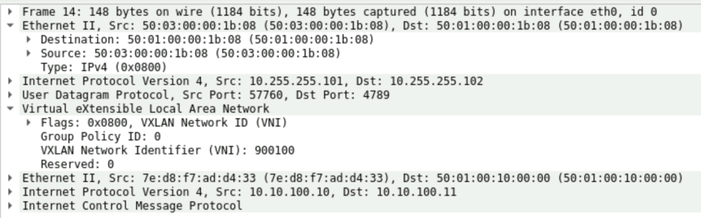
dc01-r01-leaf01# show run int lo0

interface loopback0
  description UNDERLAY
  ip address 10.255.255.3/32
  ip address 10.255.255.101/32 secondary
  ip router ospf UNDERLAY area 0.0.0.0
dc01-r01-leaf01# show ip route 10.255.255.102
10.255.255.102/32, ubest/mbest: 1/0
*via 172.16.1.1, Eth1/1, [110/81], 6d23h, ospf-UNDERLAY, intra
dc01-r01-leaf01# show cdp neigh interface eth1/1
Capability Codes: R - Router, T - Trans-Bridge, B - Source-Route-Bridge
S - Switch, H - Host, I - IGMP, r - Repeater,
V - VoIP-Phone, D - Remotely-Managed-Device,
s - Supports-STP-Dispute
Device-ID Local Intrfce Hldtme Capability Platform Port ID
dc01-spine01(98FEJSN28HN)
Eth1/1 127 R S s N9K-C9300v Eth1/1
Total entries displayed: 1The next capture point is e1/2, an exit interface on the dc01-spine01 switch. We can notice that the packet was forwarded through the spine towards the remote leaf switch without any changes. The only exception is the outer header with MAC addresses.
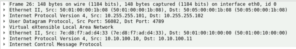
Then dc01-spine01 forwards the packet to dc01-r02-leaf01 where we have Server11 connected, and when the leaf switch receives the packet, it will strip the VXLAN header and forward the rest of the data directly to the destination host:

dc01-r02-leaf01# show mac address-table dynamic vlan 100
Legend:
        * - primary entry, G - Gateway MAC, (R) - Routed MAC, O - Overlay MAC
        age - seconds since last seen,+ - primary entry using vPC Peer-Link,
        (T) - True, (F) - False, C - ControlPlane MAC, ~ - vsan
   VLAN     MAC Address      Type      age     Secure NTFY Ports
---------+-----------------+--------+---------+------+----+------------------
*  100     5001.0010.0000   dynamic  0         F      F    Eth1/10
C  100     7ed8.f7ad.d433   dynamic  0         F      F    nve1(10.255.255.101)
That is how our request reached the destination server. Server11 replies using the same path (For simplicity, I suspended all the ECMP links). And pretty much everything will repeat the same way, but only in the reverse direction.
In the next part, I’ll cover the path for the L3 VNI forwarded packet.

Leave a comment