This stage puts customer VRFs on the four PEs and brings up one dual-stack L3VPN per provider. CustA runs over SP-A with OSPF between PE and CE, on the LDP LSPs. CustC runs over SP-B with eBGP between PE and CE, on SR-MPLS. It is the last stage of the first set of labs.
This is A-PE1’s forwarding entry for the loopback of CustA-Br1, the site behind A-PE2:
A-PE1#show ip cef vrf CustA 10.10.0.2 detail
10.10.0.2/32, epoch 0, flags [rib defined all labels]
  recursive via 10.1.0.6 label 1609
    nexthop 10.1.1.21 GigabitEthernet2 label [1104|1204]-(local:1504)
      repair: attached-nexthop 10.1.1.25 GigabitEthernet3
    nexthop 10.1.1.25 GigabitEthernet3 label [1204|1104]-(local:1504)
      repair: attached-nexthop 10.1.1.21 GigabitEthernet2
Label 1609 is the VPN label, from A-PE2’s label range 1600-1699. The outer label is the LDP label for A-PE2’s loopback: 1104 from A-P1 or 1204 from A-P2, over two equal-cost paths. Each path has a repair entry through the other, from the LFA configured in the LDP stage.
Topology file: topology.clab.yml · Addressing: ipam.md · Stage configs, 10 nodes (four PEs, six CEs): stage_configs/lab01-s5-edge-l3vpn/
VRFs, RDs and RTs
The route distinguisher (RD) is an 8-byte number the PE adds in front of each customer prefix, so two customers with the same addresses still end up as two different routes.
The route target (RT) is a tag, a BGP extended community, that the PE adds to a route when the route leaves the VRF.
The RD has three formats:
- 2-byte AS number and a 4-byte number (type 0)
- An IPv4 address and a 2-byte number (type 1)
- 4-byte AS number and a 2-byte number (type 2).
In my case, the RD is the PE’s Loopback0 address and a customer ID: 10 for CustA and 30 for CustC. The RT is the provider’s AS number and the same customer ID, with import equal to export.
| PE | VRF | RD | RT | CE |
|---|---|---|---|---|
| A-PE1 (XE) | CustA | 10.1.0.5:10 | 64501:10 | CustA-HQ |
| A-PE2 (XE) | CustA | 10.1.0.6:10 | 64501:10 | CustA-Br1 |
| A-PE2 (XE) | CustC | 10.1.0.6:30 | 64501:30 | CustC-Core1 |
| B-PE1 (XR) | CustC | 10.2.0.5:30 | 64502:30 | CustC-Core2 |
| B-PE1 (XR) | CustA | 10.2.0.5:10 | 64502:10 | CustA-Br2 |
| B-PE2 (XR) | CustC | 10.2.0.6:30 | 64502:30 | CustC-Core3 |
On A-PE1:
vrf definition CustA
 rd 10.1.0.5:10
 address-family ipv4
  route-target export 64501:10
  route-target import 64501:10
 exit-address-family
 address-family ipv6
  route-target export 64501:10
  route-target import 64501:10
 exit-address-family
!
interface GigabitEthernet4
 vrf forwarding CustA
 ip address 10.1.10.1 255.255.255.252
 ipv6 address 2001:DB8:1:20::1/64
 ip ospf 10 area 0
 ospfv3 10 ipv6 area 0
On IOS-XE, vrf forwarding removes the interface’s IPv4 and IPv6 addresses, so I added them again in the configuration snippet.
CustA: PE-CE OSPF on IOS-XE
A-PE1’s routing configuration for the VRF:
router ospf 10 vrf CustA
 router-id 10.1.10.1
 redistribute bgp 64501 subnets
!
router ospfv3 10
 address-family ipv6 unicast vrf CustA
  redistribute bgp 64501
 exit-address-family
!
router bgp 64501
 address-family ipv4 vrf CustA
  redistribute ospf 10
 exit-address-family
 address-family ipv6 vrf CustA
  redistribute ospf 10
 exit-address-family
!
The full file is A-PE1.ios.
OSPFv2 runs a separate process for the VRF, with the VRF named on the process line. Its router-id is the PE-CE interface address, 10.1.10.1. OSPFv3 uses an address family instead: address-family ipv6 unicast vrf CustA under router ospfv3 10, and ospfv3 10 ipv6 area 0 on the interface. Under address-family ipv6 vrf CustA, redistribute ospf 10 refers to the OSPFv3 process.
show ip ospf 10 neighbor needs no VRF keyword. On 16.09.08, show ospfv3 10 ipv6 neighbor prints nothing, and the neighbor appears only with vrf CustA:
A-PE1#show ip ospf 10 neighbor

Neighbor ID     Pri   State           Dead Time   Address         Interface
10.10.0.1         1   FULL/BDR        00:00:32    10.1.10.2       GigabitEthernet4
A-PE1#show ospfv3 10 ipv6 neighbor
A-PE1#show ospfv3 10 vrf CustA ipv6 neigh

          OSPFv3 10 address-family ipv6 vrf CustA (router-id 10.1.10.1)

Neighbor ID     Pri   State           Dead Time   Interface ID    Interface
10.10.0.1         1   FULL/BDR        00:00:39    2               GigabitEthernet4
CustA Routes from PE to CE
A-PE1 learns Br1’s loopback from A-RR, 10.1.0.7:
A-PE1#show ip route vrf CustA 10.10.0.2

Routing Table: CustA
Routing entry for 10.10.0.2/32
  Known via "bgp 64501", distance 200, metric 2, type internal
  Redistributing via ospf 10
  Advertised by ospf 10 subnets
  Last update from 10.1.0.6 23:18:10 ago
  Routing Descriptor Blocks:
  * 10.1.0.6 (default), from 10.1.0.7, 23:18:10 ago
      Route metric is 2, traffic share count is 1
      AS Hops 0
      MPLS label: 1609
      MPLS Flags: MPLS Required
In show bgp vpnv6 unicast vrf CustA, HQ’s own IPv6 loopback has a link-local next hop and weight 32768: it is the OSPFv3 route that redistribute ospf 10 brought in.
     Network          Next Hop            Metric LocPrf Weight Path
Route Distinguisher: 10.1.0.5:10 (default for vrf CustA)
 *>   2001:DB8:10::1/128
                      FE80::A8BB:CCFF:FE00:1310
                                                1         32768 ?
 *>i  2001:DB8:10::2/128
                      ::FFFF:10.1.0.6          1    100      0 ?
CustA-HQ has Br1’s loopback and the A-PE2 to Br1 link as inter-area routes:
      10.0.0.0/8 is variably subnetted, 5 subnets, 2 masks
O IA     10.1.10.4/30 [110/11] via 10.1.10.1, 23:33:33, Ethernet0/1
O IA     10.10.0.2/32 [110/12] via 10.1.10.1, 23:33:33, Ethernet0/1
The IPv6 loopback arrives as OI, the IPv6 table’s code for OSPF inter-area:
OI  2001:DB8:10::2/128 [110/11]
     via FE80::E00:4BFF:FEED:A503, Ethernet0/1
Both PEs run the VRF process as router ospf 10. IOS-XE sets an OSPF domain ID by default and derives it from the process number. With matching domain IDs, the receiving PE sends Br1’s routes to HQ as Type-3 Summary LSAs, which HQ installs as O IA.
HQ reaches Br1 on both stacks:
CustA-HQ#ping 10.10.0.2 source Loopback0
Type escape sequence to abort.
Sending 5, 100-byte ICMP Echos to 10.10.0.2, timeout is 2 seconds:
Packet sent with a source address of 10.10.0.1
!!!!!
Success rate is 100 percent (5/5), round-trip min/avg/max = 1/2/4 ms
CustA-HQ#ping 2001:db8:10::2 source Loopback0
Type escape sequence to abort.
Sending 5, 100-byte ICMP Echos to 2001:DB8:10::2, timeout is 2 seconds:
Packet sent with a source address of 2001:DB8:10::1
!!!!!
Success rate is 100 percent (5/5), round-trip min/avg/max = 1/1/2 ms
CustC: PE-CE eBGP on IOS-XR
B-PE1’s route-policy and BGP configuration:
route-policy PASS
  pass
end-policy
!
router bgp 64502
 vrf CustC
  rd 10.2.0.5:30
  address-family ipv4 unicast
  !
  address-family ipv6 unicast
  !
  neighbor 10.2.12.2
   remote-as 64530
   address-family ipv4 unicast
    route-policy PASS in
    route-policy PASS out
    as-override
   !
  !
  neighbor 2001:db8:2:24::2
   remote-as 64530
   address-family ipv6 unicast
    route-policy PASS in
    route-policy PASS out
    as-override
   !
  !
 !
!
The block above is trimmed to the CustC part; the full file is B-PE1.ios.
IOS-XR sends and accepts no routes on an eBGP session until a route-policy is applied in each direction, so both neighbors carry route-policy PASS in and out. B-PE2.ios has the same block for CustC-Core3.
CustC uses AS 64530 at all three sites. B-PE1 holds Core3’s loopback with the AS path 64530:
   Network            Next Hop            Metric LocPrf Weight Path
Route Distinguisher: 10.2.0.5:30 (default for vrf CustC)
*> 10.30.0.2/32       10.2.12.2                0             0 64530 i
*>i10.30.0.3/32       10.2.0.6                 0    100      0 64530 i

Processed 2 prefixes, 2 paths
Core2 rejects a route whose AS path contains its own AS, 64530. as-override on B-PE1 replaces 64530 with 64502 in the routes it sends to Core2. Core2 installs Core3’s IPv4 loopback through B-PE1:
      10.0.0.0/8 is variably subnetted, 4 subnets, 2 masks
B        10.30.0.3/32 [20/0] via 10.2.12.1, 23:21:21
The IPv6 loopback comes in through B-PE1’s link-local address:
B   2001:DB8:30::3/128 [20/0]
     via FE80::E00:54FF:FE99:D404, GigabitEthernet2
Core2 reaches Core3 on both stacks:
CustC-Core2#ping 10.30.0.3 sourc lo0
Type escape sequence to abort.
Sending 5, 100-byte ICMP Echos to 10.30.0.3, timeout is 2 seconds:
Packet sent with a source address of 10.30.0.2
!!!!!
Success rate is 100 percent (5/5), round-trip min/avg/max = 3/4/7 ms
CustC-Core2#ping 2001:db8:30::3 sour lo0
Type escape sequence to abort.
Sending 5, 100-byte ICMP Echos to 2001:DB8:30::3, timeout is 2 seconds:
Packet sent with a source address of 2001:DB8:30::2
!!!!!
Success rate is 100 percent (5/5), round-trip min/avg/max = 2/4/8 ms
Labels on the SP-B Path
B-PE1’s forwarding entry for Core3’s loopback:
   via 10.2.0.6/32, 5 dependencies, recursive [flags 0x6000]
    path-idx 0 NHID 0x0 [0xdd57248 0x0]
    recursion-via-/32
    next hop VRF - 'default', table - 0xe0000000
    next hop 10.2.0.6/32 via 16600/0/21
     next hop 10.2.1.21/32 Gi0/0/0/0    labels imposed {16600 24006}
The outer label 16600 is B-PE2’s prefix-SID, index 600 on an SRGB that starts at 16000. The inner label 24006 is B-PE2’s VPN label for 10.30.0.3/32. The next hop 10.2.1.21 is B-P1.
In the other direction, B-PE2’s next hop is 10.2.1.49, which is also B-P1:
   via 10.2.0.5/32, 5 dependencies, recursive [flags 0x6000]
    path-idx 0 NHID 0x0 [0xe2501d8 0x0]
    recursion-via-/32
    next hop VRF - 'default', table - 0xe0000000
    next hop 10.2.0.5/32 via 16500/0/21
     next hop 10.2.1.49/32 Gi0/0/0/4    labels imposed {16500 24008}
The IPv6 route to Core2’s loopback has the next hop ::ffff:10.2.0.5, B-PE1’s IPv4 loopback in IPv4-mapped form, so it resolves over the same IPv4 prefix-SID label, 16500:
   via ::ffff:10.2.0.5/128, 5 dependencies, recursive [flags 0x6000]
    path-idx 0 NHID 0x0 [0xe2501d8 0x0]
    recursion-via-/128
    next hop VRF - 'default', table - 0xe0000000
    next hop ::ffff:10.2.0.5/128 via 16500/0/21
     next hop 10.2.1.49/32 Gi0/0/0/4    labels imposed {16500 24009}
The Orphan Sites
Each customer also has one site attached to the other provider: CustA-Br2 behind B-PE1 and CustC-Core1 behind A-PE2. These are the orphan sites.
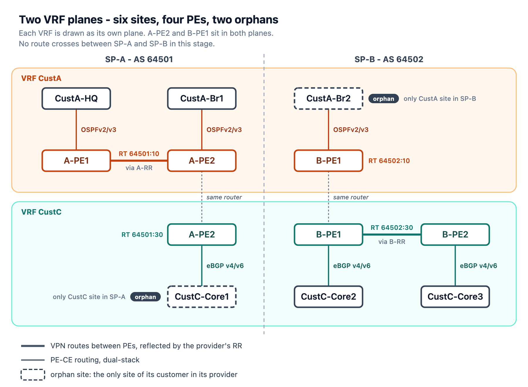
B-PE1’s OSPF and BGP configuration for Br2:
router ospf 10
 vrf CustA
  router-id 10.2.10.1
  redistribute bgp 64502
  area 0
   interface GigabitEthernet0/0/0/2
   !
  !
 !
!
router ospfv3 10
 vrf CustA
  redistribute bgp 64502
  area 0
   interface GigabitEthernet0/0/0/2
   !
  !
 !
!
router bgp 64502
 vrf CustA
  rd 10.2.0.5:10
  address-family ipv4 unicast
   redistribute ospf 10
  !
  address-family ipv6 unicast
   redistribute ospfv3 10
  !
 !
!
B-PE1 redistributes Br2’s IPv6 routes into BGP with redistribute ospfv3 10; A-PE1 uses redistribute ospf 10 for the same job.
Br2’s OSPFv2 and OSPFv3 adjacencies to B-PE1 are FULL:
CustA-Br2#show ip ospf neigh

Neighbor ID     Pri   State           Dead Time   Address         Interface
10.2.10.1         1   FULL/BDR        00:00:33    10.2.10.1       Ethernet0/1
CustA-Br2#show ipv6 ospf neigh

            OSPFv3 Router with ID (10.10.0.3) (Process ID 1)

Neighbor ID     Pri   State           Dead Time   Interface ID    Interface
10.2.0.5          1   FULL/BDR        00:00:37    9               Ethernet0/1
With no router-id configured, the IOS-XR OSPFv3 VRF process took the global Loopback0, 10.2.0.5. IOS-XE on A-PE1 took the VRF interface address, 10.1.10.1.
B-PE1’s CustA VRF holds only the link to Br2 and Br2’s loopback:
C    10.2.10.0/30 is directly connected, 23:42:02, GigabitEthernet0/0/0/2
L    10.2.10.1/32 is directly connected, 23:42:02, GigabitEthernet0/0/0/2
O    10.10.0.3/32 [110/2] via 10.2.10.2, 23:19:00, GigabitEthernet0/0/0/2
Br2 cannot reach CustA-HQ:
CustA-Br2#ping 10.10.0.1 sour lo0
Type escape sequence to abort.
Sending 5, 100-byte ICMP Echos to 10.10.0.1, timeout is 2 seconds:
Packet sent with a source address of 10.10.0.3
...
Success rate is 0 percent (0/3)
Core1’s IPv4 session to A-PE2 is up with 0 prefixes received:
Neighbor        V           AS MsgRcvd MsgSent   TblVer  InQ OutQ Up/Down  State/PfxRcd
10.1.12.1       4        64501    1575    1575        4    0    0 23:45:58        0
The IPv6 session to A-PE2 also has 0 prefixes received:
Neighbor        V           AS MsgRcvd MsgSent   TblVer  InQ OutQ Up/Down  State/PfxRcd
2001:DB8:1:24::1
                4        64501    1571    1573        3    0    0 23:45:03        0
A-RR has five prefixes under three RDs, all from SP-A PEs, with Core1’s loopback under 10.1.0.6:30:
   Network            Next Hop            Metric LocPrf Weight Path
Route Distinguisher: 10.1.0.5:10
Route Distinguisher Version: 5
*>i10.1.10.0/30       10.1.0.5                 0    100      0 ?
*>i10.10.0.1/32       10.1.0.5                 2    100      0 ?
Route Distinguisher: 10.1.0.6:10
Route Distinguisher Version: 4
*>i10.1.10.4/30       10.1.0.6                 0    100      0 ?
*>i10.10.0.2/32       10.1.0.6                 2    100      0 ?
Route Distinguisher: 10.1.0.6:30
Route Distinguisher Version: 6
*>i10.30.0.1/32       10.1.0.6                 0    100      0 64530 i

Processed 5 prefixes, 5 paths
B-RR has four prefixes under three RDs, all from SP-B PEs, with Br2’s loopback under 10.2.0.5:10:
   Network            Next Hop            Metric LocPrf Weight Path
Route Distinguisher: 10.2.0.5:10
Route Distinguisher Version: 9
*>i10.2.10.0/30       10.2.0.5                 0    100      0 ?
*>i10.10.0.3/32       10.2.0.5                 2    100      0 ?
Route Distinguisher: 10.2.0.5:30
Route Distinguisher Version: 11
*>i10.30.0.2/32       10.2.0.5                 0    100      0 64530 i
Route Distinguisher: 10.2.0.6:30
Route Distinguisher Version: 5
*>i10.30.0.3/32       10.2.0.6                 0    100      0 64530 i

Processed 4 prefixes, 4 paths
A BGP-Free Core
The P routers run no BGP. A-P1:
A-P1#show ip bgp summary
% BGP not active
B-P1:
RP/0/RP0/CPU0:B-P1#show bgp vpnv4 uni sum
Sun Jun 21 13:39:40.847 UTC
% BGP instance 'default' not active
Verification
The commands behind this post, as run:
A-PE1#show ip ospf 10 neighbor
A-PE1#show ospfv3 10 ipv6 neighbor
A-PE1#show ospfv3 10 vrf CustA ipv6 neigh
A-PE1#show bgp vpnv6 unicast vrf CustA
A-PE1#show ip route vrf CustA 10.10.0.2
A-PE1#show ip cef vrf CustA 10.10.0.2 detail

CustA-HQ#show ip route ospf
CustA-HQ#show ipv6 route ospf
CustA-HQ#ping 10.10.0.2 source Loopback0
CustA-HQ#ping 2001:db8:10::2 source Loopback0

RP/0/RP0/CPU0:B-PE1#show bgp vrf CustC ipv4 unicast
RP/0/RP0/CPU0:B-PE1#show cef vrf CustC 10.30.0.3 detail
RP/0/RP0/CPU0:B-PE1#show route vrf CustA
RP/0/RP0/CPU0:B-PE2#show cef vrf CustC 10.30.0.2 detail
RP/0/RP0/CPU0:B-PE2#show cef vrf CustC ipv6 2001:db8:30::2 detail

CustC-Core2#show ip route bgp
CustC-Core2#show ipv6 route bgp
CustC-Core2#ping 10.30.0.3 sourc lo0
CustC-Core2#ping 2001:db8:30::3 sour lo0

CustA-Br2#show ip ospf neigh
CustA-Br2#show ipv6 ospf neigh
CustA-Br2#ping 10.10.0.1 sour lo0

CustC-Core1#show ip bgp sum
CustC-Core1#show bgp ipv6 uni sum

RP/0/RP0/CPU0:A-RR#show bgp vpnv4 unicast

RP/0/RP0/CPU0:B-RR#show bgp vpnv4 un

A-P1#show ip bgp summary

RP/0/RP0/CPU0:B-P1#show bgp vpnv4 uni sum
What’s Next
This lab concludes the first set of labs I plan to complete in this topology. The second part will stay mostly on SP-A: RSVP-TE with inter-area tunnels, SR-LDP interworking, VPWS and EVPN, a multicast core, and mVPN Profile 0.
The two orphan sites will be connected in the third part: CustC-Core1 through Inter-AS Option A, and CustA-Br2 through Option B, with the RT rewritten at the ASBR.


Leave a comment