During this step, we’re building an underlay foundation for the SP-A provider network, which runs OSPF as its IGP.
This post covers the design decisions, configuration, and verification for SP-A’s IGP: dual-stack OSPFv2 + OSPFv3 in a multi-area topology, running on IOS-XE with an IOS-XR as a future RR.
The Design
SP-A has 8 nodes: 4 P-routers (core), 2 PE-routers (edge), 1 ASBR (Inter-AS border), and 1 RR (route reflector, control-plane only). Flat single-area OSPF would converge fine at this size. But the design target is a real legacy core, and I want the multi-area OSPF behaviour that comes with it.
SPF scope. Every router runs SPF across the entire topology. A link flap at the PE edge forces every router in the backbone to recompute. Multi-area limits SPF computation to within the affected area. The backbone only sees a Type-3 Summary LSA update, not a full topology event.
LSDB size. In a single-area design, every router holds the complete topology, including the transit links of every PE-to-P connection. With hundreds of PEs, this becomes a memory and convergence problem. Less so these days, since routers carry far more memory and CPU, but a single-area design can still create unexpected problems at large scale.
Failure domain isolation. A PE covers the edge side of this SP network. Simple events occurring on the edge of the network should not disrupt the core.
In this lab, I picked a multi-area design – a backbone plus two edge areas: Area 0 (backbone) holds the P-routers, RR, and ASBR – the stable transit core.
Area 1 is the A-PE1 edge cloud (behind A-P1/A-P2).
Area 2 is the A-PE2 edge cloud (behind A-P3/A-P4).
The four P-routers are ABRs and summarize reachability between areas using Type-3 Summary LSAs.
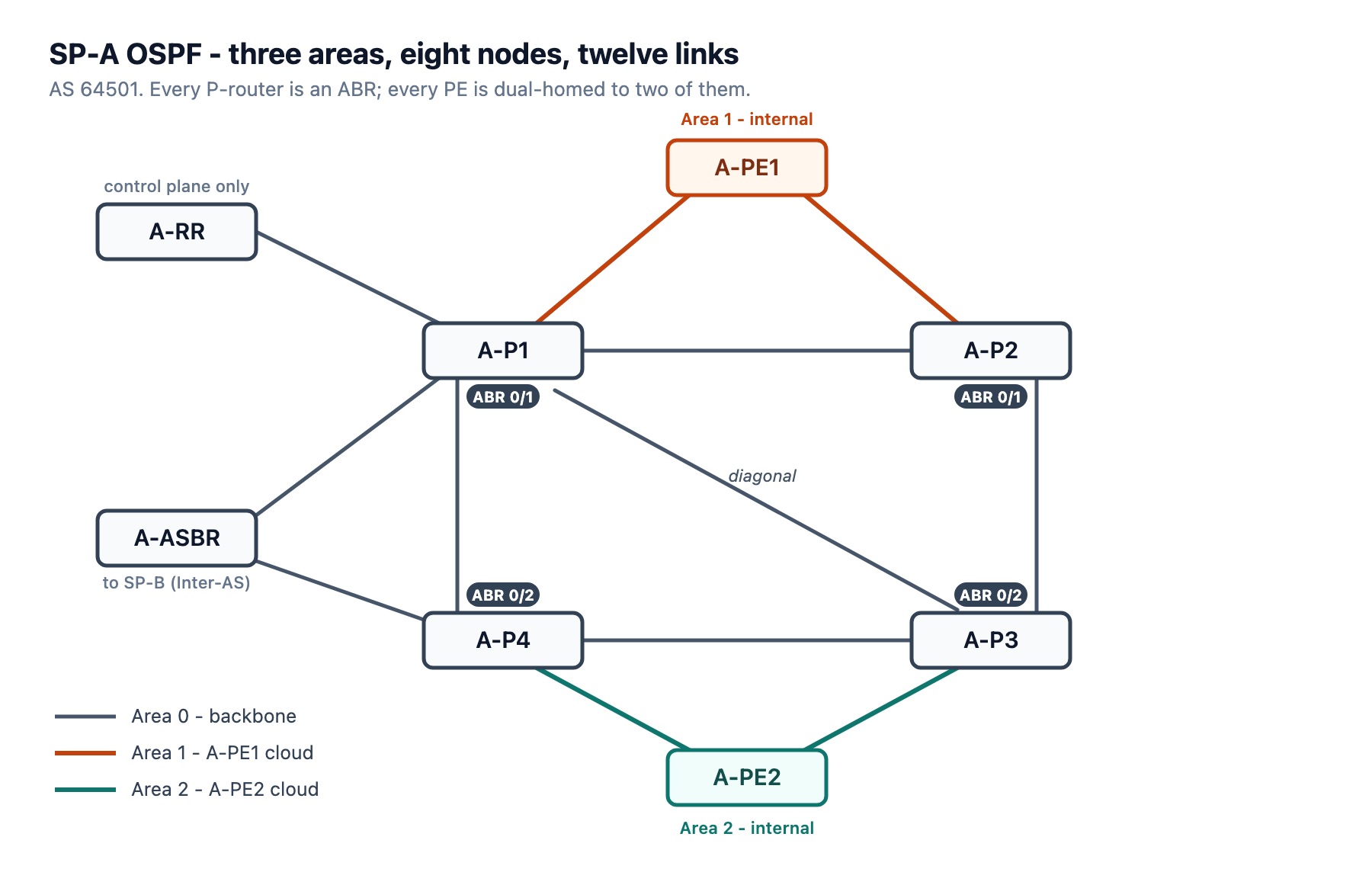
The four P-routers form a full square with one diagonal across it, so the backbone survives any single core link failure. A-RR hangs off A-P1 alone – it is control-plane only and carries no transit.
A-ASBR is dual-homed to A-P1 and A-P4.
Each PE is dual-homed to two different ABRs, and those four PE uplinks are the only interfaces in SP-A that are not in Area 0.
Topology file: topology.clab.yml · Addressing: ipam.md · Stage configs: stage_configs/lab01-s1a-spa-ospf/
Why Four ABRs?
A-P1 through A-P4 are all ABRs. A-P1 and A-P2 cover Area 0 and Area 1, A-P3 and A-P4 are responsible for Area 0 and Area 2. This gives each PE dual uplinks to the backbone through two independent ABRs.
If A-P1 fails, A-PE1 still has A-P2 as an ABR. ECMP at the PE level falls out of the equal-cost paths through those independent ABRs. On A-PE1, prefixes reached through the far ABRs (A-P3 at 10.1.0.3, A-PE2 at 10.1.0.6) show two next-hops at identical cost – 10.1.1.25 via A-P2 and 10.1.1.21 via A-P1:
A-PE1#show ip route   ← O IA rows only
O IA     10.1.0.3/32 [110/3] via 10.1.1.25, 00:21:14, GigabitEthernet3   ← via A-P2
                     [110/3] via 10.1.1.21, 01:28:54, GigabitEthernet2   ← via A-P1
O IA     10.1.0.6/32 [110/4] via 10.1.1.25, 00:21:14, GigabitEthernet3
                     [110/4] via 10.1.1.21, 01:24:32, GigabitEthernet2
Where the two uplinks tie on cost, the route is ECMP; where they don’t, the second ABR is a hot standby one SPF run away.
Network Type: Point-to-Point Everywhere
All links in SP-A are Ethernet, but all OSPF interfaces are configured as network point-to-point. On IOS-XE, this is ip ospf network point-to-point and ospfv3 network point-to-point per interface. On IOS-XR, it’s network point-to-point inside the OSPF interface stanza.
The reason: every link in this topology has exactly two routers. The default Ethernet network type is broadcast, which triggers DR/BDR election. A DR election on a link with exactly two routers wastes hello exchanges and delays adjacency formation without providing any benefit. Point-to-point skips the election entirely, forms adjacency directly, and produces cleaner Type-1 Router LSAs.
Passive Interfaces
Every router uses passive-interface default with explicit no passive-interface for transit links. Loopback0 is left passive – it participates in OSPF and its prefix is advertised, but OSPF never sends hellos from it because there’s no neighbor to form an adjacency with.
CE-facing interfaces on A-PE1 (Gi4, Gi5) and A-PE2 (Gi4, Gi5, Gi6) are also left passive and excluded from OSPF entirely. They have no OSPF configuration, so no adjacency attempt is made toward the CEs.
The IOS-XR Syntax Difference: passive enable vs passive-interface
On IOS-XR OSPFv2, passive enable at the process level sets passive as the default for all interfaces. Then passive disable reactivates the specific transit interface.
! Node: A-RR
! Type: XR
router ospf 1
 router-id 10.1.0.7
 passive enable
 area 0
  interface Loopback0
  !
  interface GigabitEthernet0/0/0/0 ! to A-P1
   passive disable
   network point-to-point
  !
 !
!
For OSPFv3 on IOS-XR, the keyword is simply passive (without enable):
router ospfv3 1
 router-id 10.1.0.7
 passive
 area 0
  interface Loopback0
  !
  interface GigabitEthernet0/0/0/0
   passive disable
   network point-to-point
  !
 !
!
Full Configuration: SP-A OSPF (Stage 1A)
All eight node configurations are in the lab repo, one file per router: stage_configs/lab01-s1a-spa-ospf/. They are stage deltas, not full configs – protocol logic only, applied on top of the per-node baselines in lab_configs/, which carry the addressing.
LSDB review after the configuration
LSDB should be formed right after the convergence, and I’ll take A-P1 as an example:
A-P1#show ip ospf database

            OSPF Router with ID (10.1.0.1) (Process ID 1)

                Router Link States (Area 0)

Link ID         ADV Router      Age         Seq#       Checksum Link count
10.1.0.1        10.1.0.1        862         0x80000041 0x000C91 11
10.1.0.2        10.1.0.2        1412        0x80000036 0x0064E0 5
10.1.0.3        10.1.0.3        1648        0x8000000B 0x006D8A 7
10.1.0.4        10.1.0.4        1720        0x8000000A 0x00A701 7
10.1.0.7        10.1.0.7        811         0x80000005 0x00EE7D 3
10.1.0.8        10.1.0.8        1718        0x80000032 0x00CFC5 5

                Summary Net Link States (Area 0)

Link ID         ADV Router      Age         Seq#       Checksum
10.1.0.5        10.1.0.1        1365        0x80000003 0x0070AC
10.1.0.5        10.1.0.2        1274        0x80000001 0x006EAF
10.1.0.6        10.1.0.3        1152        0x80000003 0x005ABF
10.1.0.6        10.1.0.4        1211        0x80000003 0x0054C4
10.1.1.20       10.1.0.1        93          0x8000002F 0x005A8A
10.1.1.20       10.1.0.2        1274        0x80000001 0x00BA56
10.1.1.24       10.1.0.1        1283        0x80000001 0x009875
10.1.1.24       10.1.0.2        1412        0x80000001 0x008885
10.1.1.28       10.1.0.3        1893        0x80000003 0x0056B0
10.1.1.28       10.1.0.4        950         0x80000003 0x005AAA
10.1.1.32       10.1.0.3        1152        0x80000003 0x0038C9
10.1.1.32       10.1.0.4        1720        0x80000003 0x0028D9

                Router Link States (Area 1)

Link ID         ADV Router      Age         Seq#       Checksum Link count
10.1.0.1        10.1.0.1        1365        0x80000030 0x0090FB 2
10.1.0.2        10.1.0.2        1275        0x80000003 0x006B44 2
10.1.0.5        10.1.0.5        1274        0x8000000B 0x00D641 5

                Summary Net Link States (Area 1)

Link ID         ADV Router      Age         Seq#       Checksum
10.1.0.1        10.1.0.1        93          0x8000002F 0x0036BF
10.1.0.1        10.1.0.2        1412        0x80000001 0x00968B
10.1.0.2        10.1.0.1        1103        0x8000002E 0x0038BC
10.1.0.2        10.1.0.2        1412        0x80000001 0x00829F
10.1.0.3        10.1.0.1        1867        0x80000003 0x00849A
10.1.0.3        10.1.0.2        1412        0x80000001 0x00829D
10.1.0.4        10.1.0.1        1608        0x80000003 0x007AA3
10.1.0.4        10.1.0.2        1412        0x80000001 0x00829B
10.1.0.6        10.1.0.1        1103        0x80000003 0x0070AA
10.1.0.6        10.1.0.2        1412        0x80000001 0x006EAD
The Area 1 summary list runs to 34 entries – every backbone loopback and every backbone transit /30, each advertised twice, once by A-P1 and once by A-P2.
Four things visible here:
- Area 0 Router LSA with link count 11 – A-P1’s backbone topology: Loopback0 as a stub, plus five backbone P2P interfaces, each of which contributes both a point-to-point link and a stub link for its
/30(5×2 + 1 = 11). Link count is not interface count. This is what other Area 0 routers use for SPF. - Area 0 Summary LSA for 10.1.0.5 – both A-P1 and A-P2 advertise A-PE1’s loopback into the backbone (one Type-3 each), the dual-ABR redundancy showing up directly in the LSDB. Other Area 0 nodes don’t know Area 1’s topology; they just know how to reach 10.1.0.5 via either ABR.
- Area 1 Router LSA with link count 2 – A-P1’s Area 1 presence: the single P2P link to A-PE1 (one point-to-point link plus its stub). A-P2 appears here too with link count 2. Routers in Area 1 know only this topology segment.
- Area 1 Summary LSAs for the backbone prefixes – A-P1 floods the backbone loopbacks and transit
/30s into Area 1 as Type-3 summaries (A-P2 floods the same set in parallel). A-PE1 doesn’t run SPF for Area 0, it just installs these summaries as O IA routes.
The OSPFv3 database mirrors this exactly, with Inter Area Prefix LSAs (the v3 equivalent of Type-3 summaries) carrying the IPv6 loopbacks.
Verification
From A-PE1, which is entirely in Area 1, every backbone prefix arrives as O IA.
A-PE1#show ip route   ← O IA rows only
O IA     10.1.0.1/32 [110/2] via 10.1.1.21, 01:28:54, GigabitEthernet2
O IA     10.1.0.2/32 [110/2] via 10.1.1.25, 00:21:14, GigabitEthernet3
O IA     10.1.0.3/32 [110/3] via 10.1.1.25, 00:21:14, GigabitEthernet3
                     [110/3] via 10.1.1.21, 01:28:54, GigabitEthernet2
O IA     10.1.0.4/32 [110/3] via 10.1.1.21, 01:28:54, GigabitEthernet2
O IA     10.1.0.6/32 [110/4] via 10.1.1.25, 00:21:14, GigabitEthernet3
                     [110/4] via 10.1.1.21, 01:24:32, GigabitEthernet2
O IA     10.1.0.7/32 [110/3] via 10.1.1.21, 01:20:39, GigabitEthernet2
O IA     10.1.0.8/32 [110/3] via 10.1.1.21, 01:28:54, GigabitEthernet2
A-PE1 has no intra-area view of the backbone topology – it only knows the summaries.
The ECMP on 10.1.0.3/32 and 10.1.0.6/32 shows that two ABR paths exist with equal cost.
IPv6 follows the same pattern – all routes arrive as OI (OSPFv3 inter-area):
A-PE1#show ipv6 route   ← OI rows only
OI  2001:DB8:1::1/128 [110/1]
     via FE80::E00:23FF:FE0E:9404, GigabitEthernet2
OI  2001:DB8:1::2/128 [110/1]
     via FE80::E00:CCFF:FEF8:3E03, GigabitEthernet3
OI  2001:DB8:1::3/128 [110/2]
     via FE80::E00:23FF:FE0E:9404, GigabitEthernet2
     via FE80::E00:CCFF:FEF8:3E03, GigabitEthernet3
OI  2001:DB8:1::4/128 [110/2]
     via FE80::E00:23FF:FE0E:9404, GigabitEthernet2
OI  2001:DB8:1::6/128 [110/3]
     via FE80::E00:23FF:FE0E:9404, GigabitEthernet2
     via FE80::E00:CCFF:FEF8:3E03, GigabitEthernet3
OI  2001:DB8:1::7/128 [110/2]
     via FE80::E00:23FF:FE0E:9404, GigabitEthernet2
OI  2001:DB8:1::8/128 [110/2]
     via FE80::E00:23FF:FE0E:9404, GigabitEthernet2
All 7 remote loopbacks reachable dual-stack. Transit /30 and /64 subnets are present in the RIB at this stage. Removing them is an optimization, covered in a later post on IGP tuning.
Summary
A-P1 shows a Router LSA with link count 11 in Area 0 and another with link count 2 in Area 1.
A-PE1 only ever sees the second one. Its SPF runs across a two-link area while the backbone routers compute over all eleven, and a flap on either side stays within its own area. A-PE2 sits the same way inside Area 2.
Everything backbone-side arrives at A-PE1 as a Type-3 summary and lands in the RIB as O IA. Both of its ABRs advertise the same set, which is why 10.1.0.3/32 and 10.1.0.6/32 turn up twice at equal cost.
That’s the foundation LDP and BGP need before I layer them on in the next stages: loopbacks that stay reachable.
The next post covers SP-B’s IGP: IS-IS, Level-2 only, dual-stack through Multi-Topology.


Leave a Reply