SP-A uses OSPF because I wanted to cover both IGPs listed in the CCIE SP blueprint, and at the same time, it represents the “legacy services” ISP. SP-B uses IS-IS – the dominant IGP choice for modern carrier networks that run MPLS at scale and plan to run Segment Routing beyond that.
This post covers why IS-IS, how it’s configured across a mixed IOS-XE / IOS-XR core, the Multi-Topology difference that splits the two platforms, and what the LSDB looks like when it’s working correctly.
Why IS-IS? Comparison with OSPF
Both protocols solve the same problem; however, IS-IS has some distinct differences compared to OSPF:
IS-IS doesn’t carry IP natively. It runs directly over Layer 2; OSPF runs over IP. Even so, IOS-XE brings an IS-IS adjacency up only when both ends share an IPv4 subnet.
The two protocols extend differently. IS-IS carries new information in TLVs, so SR-MPLS prefix-SIDs, TLV 135 extended IP reachability, TLV 22 extended IS reachability, Flex-Algo definitions and SRv6 locators are all additions to one existing structure. OSPFv2 carries the same information in Opaque LSAs. IPv6 handling is slightly different. IS-IS treats it as more TLVs in the same LSPs over the same adjacency, with the link-local address that neighbours use as the IPv6 next-hop advertised in the IPv6 interface address TLV (232) in the hello. OSPFv3 went the other way: RFC 5340 defines a separate protocol, with renumbered LSA types and the protocol itself running on link-local addressing, and IPv4 support was added into it as an address-family extension.
Dual-stack processing. One IS-IS process carries IPv4 and IPv6 through Multi-Topology (MT), on a single adjacency. SP-A takes the classic OSPF split instead – OSPFv2 for IPv4, OSPFv3 for IPv6, two processes with two LSDBs and two sets of adjacencies and timers. RFC 5838 gives OSPFv3 address families, so one OSPFv3 process can carry IPv4 as well, and on paper the two protocols sit close to parity here. The single-process model has IS-IS with one adjacency for both address families, with the MT feature enabled: both ends have to agree.
For SP-B, the choice is also forward-looking; IS-IS carries IPv6 reachability for both the SR-MPLS and the SRv6 dataplane.
Single Level IS-IS
IS-IS has two routing levels: Level-1 (intra-area, like OSPF intra-area) and Level-2 (inter-area, like OSPF backbone). In an enterprise network with multiple IS-IS areas, L1/L2 routers redistribute between them. In a service provider core, this is unnecessary complexity.
All SP-B nodes are configured as Level-2 only (is-type level-2-only). The entire SP-B IS domain is a single flat L2 domain. Every router participates in the same L2 LSDB flooding. The IS-IS area address (49.0001) is present in the NET for identification purposes.
Wide Metrics importance
Standard IS-IS metrics use a 6-bit field: maximum per-link metric is 63, maximum path metric is 1023. These limits were designed for 1990s Ethernet. They are incompatible with:
- Segment Routing: the IPv4 prefix-SID rides as a sub-TLV of TLV 135 (Extended IP Reachability), and TLV 135 only exists under wide metrics. Narrow metrics leave nowhere to carry it.
- Traffic Engineering: TE constraint propagation uses TLV 22 (Extended IS Reachability). Same dependency.
- Flex-Algo: the link delay and administrative-group values a Flex-Algo constrains on are sub-TLVs of TLV 22.
Wide metrics (metric-style wide) widen the per-link metric to 24 bits and the prefix metric to 32 bits. The highest link metric usable in an SPF is 16,777,214: all-ones is reserved to mean the link must be skipped, which is why an IOS-XR max-metric link advertises Metric: 16777214 and stops one short. Every router in SP-B is configured with wide metrics from Stage 1B, because the upcoming stages won’t work without it.
Topology: 8 Nodes, Single Flat L2 Domain
SP-B has 8 nodes – 3 XRv9k (B-P1, B-PE1, B-PE2), 4 CSR1000v (B-P2, B-P3, B-P4, B-ASBR), and 1 XRd-CP (B-RR). All participate in the same IS-IS Level-2 domain.
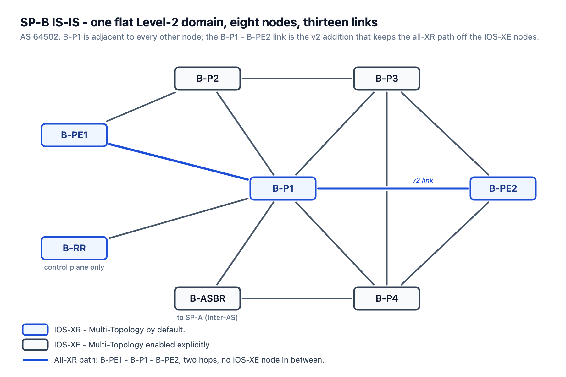
The hub is B-P1, with 7 neighbors: B-P2, B-P3, B-P4, B-PE1, B-PE2, B-RR, and B-ASBR. One of those adjacencies, the B-P1 ↔ B-PE2 link, is the v2 addition that makes the all-XR transit path continuous; we’ll use it later to avoid crossing IOS-XE routers.
Topology file: topology.clab.yml · Addressing: ipam.md · Stage configs: stage_configs/lab01-s1b-spb-isis/
RP/0/RP0/CPU0:B-P1#show isis neigh
Sun Apr 26 13:50:59.611 UTC

IS-IS 1 neighbors:
System Id      Interface        SNPA           State Holdtime Type IETF-NSF
B-P3           Gi0/0/0/1        *PtoP*         Up    29       L2   Capable
B-P2           Gi0/0/0/0        *PtoP*         Up    28       L2   Capable
B-PE2          Gi0/0/0/6        *PtoP*         Up    27       L2   Capable
B-P4           Gi0/0/0/2        *PtoP*         Up    23       L2   Capable
B-RR           Gi0/0/0/4        *PtoP*         Up    22       L2   Capable
B-ASBR         Gi0/0/0/5        *PtoP*         Up    21       L2   Capable
B-PE1          Gi0/0/0/3        *PtoP*         Up    28       L2   Capable

Total neighbor count: 7
All 7 neighbors UP, all L2, all P2P.
Point-to-Point Network Type: Skip the DIS Election
IS-IS on broadcast networks (Ethernet) elects a Designated Intermediate System (DIS) and creates a Pseudonode LSP to represent the LAN segment. This adds LSP processing overhead and a DR-equivalent role that has to be re-elected on failure.
Every link in SP-B is a P2P link between exactly two routers. Configuring point-to-point (or isis network point-to-point on IOS-XE) skips the DIS election, uses a 3-way handshake instead of the broadcast adjacency procedure, and produces a simpler LSDB with no pseudonode LSPs.
IOS-XE vs IOS-XR: The Dual-Stack Configuration Difference
XE and XR are not aligned with the default configuration of the dual-stack IS-IS process.
IOS-XE (CSR1000v) defaults to Single-Topology (ST). In Single-Topology mode, IS-IS assumes the IPv4 and IPv6 topologies have identical links and identical metrics. If any link is IPv4-only or IPv6-only, ST breaks. To support independent IPv4 and IPv6 topologies, you must explicitly enable Multi-Topology:
! Node: B-P2
! Stage: S1B
! Type: XE
!
router isis
 net 49.0001.0102.0000.0002.00
 is-type level-2-only
 metric-style wide
 log-adjacency-changes
 passive-interface Loopback0
 address-family ipv6
  multi-topology
 exit-address-family
IOS-XR defaults to Multi-Topology. No explicit MT configuration is needed. The protocol natively maintains separate SPF trees for each address family. The configuration is per-interface and per-address-family:
! Node: B-P1
! Stage: S1B
! Type: XR
!
router isis 1
 net 49.0001.0102.0000.0001.00
 is-type level-2-only
 address-family ipv4 unicast
  metric-style wide
 !
 address-family ipv6 unicast
  metric-style wide
 !
 interface Loopback0
  passive
  address-family ipv4 unicast
  !
  address-family ipv6 unicast
  !
 !
 interface GigabitEthernet0/0/0/0
  point-to-point
  address-family ipv4 unicast
  !
  address-family ipv6 unicast
  !
 !
The block is trimmed to Loopback0 and the first transit interface. B-P1’s other six, GigabitEthernet0/0/0/1 through 0/0/0/6, are not shown here and repeat the GigabitEthernet0/0/0/0 stanza line for line with only the interface name changing – the full file is B-P1.ios in the repo.
The passive keyword on Loopback0 in the XR IS-IS process is the XR equivalent of passive-interface Loopback0 on XE. It must be at the interface level within the IS-IS process, not at the process level or router level.
Why MT matters for adjacency health
Both ends have to run the same topology mode, or the adjacency does not come up. The exception is multi-topology transition mode: a router in transition mode peers with a single-topology neighbor, and both address families work.
The diagnostic is show isis database detail: look for TLV 229 (Multi-Topology) entries. A correctly configured MT node advertises MTID 0 (IPv4 Unicast) and MTID 2 (IPv6 Unicast) in TLV 229. If one end is missing MTID 2, the IPv6 topology is not synchronized.
The NET Address Scheme
Every IS-IS router needs a Network Entity Title (NET). The format is: <area>.<system-id>.00
For SP-B:
- Area:
49.0001 - System-ID:
0102marks SP-B, and the last digit is the router’s loopback host octet
| Node | Loopback | NET |
|---|---|---|
| B-P1 | 10.2.0.1 | 49.0001.0102.0000.0001.00 |
| B-P2 | 10.2.0.2 | 49.0001.0102.0000.0002.00 |
| B-P3 | 10.2.0.3 | 49.0001.0102.0000.0003.00 |
| B-P4 | 10.2.0.4 | 49.0001.0102.0000.0004.00 |
| B-PE1 | 10.2.0.5 | 49.0001.0102.0000.0005.00 |
| B-PE2 | 10.2.0.6 | 49.0001.0102.0000.0006.00 |
| B-RR | 10.2.0.7 | 49.0001.0102.0000.0007.00 |
| B-ASBR | 10.2.0.8 | 49.0001.0102.0000.0008.00 |
The encoding: 10.2.0.N → 0102.0000.000N.
What the LSDB Looks Like
The IS-IS LSDB is organised differently from the OSPF LSDB. In OSPF, separate LSA types carry topology information vs. prefix information. In IS-IS, both live in the same LSP (Link State PDU), though wide metrics and MT split them into separate TLVs.
The capture below is from B-P1, so these are the IOS-XR renderings. IOS-XE prints the same TLVs with different labels, and the B-ASBR capture further down shows two of them side by side.
NLPID: 0xcc,NLPID: 0x8e– TLV 129, Protocols Supported: this router carries IPv4 (0xCC) and IPv6 (0x8E). XR prints one line per protocol; XE folds both into a singleNLPID: 0xCC 0x8E.MT: Standard (IPv4 Unicast),MT: IPv6 Unicast– TLV 229, Multi-Topology. Two MTIDs advertised, so each address family gets its own topology. XE renders the same TLV asTopology: IPv4 (0x0)/IPv6 (0x2).IS-Extended– TLV 22, Extended IS Reachability. The neighbour adjacencies, with wide metrics.MT (IPv6 Unicast) IS-Extended– TLV 222, MT-ISN: the same adjacencies as they exist in the IPv6 topology. XE prints these asIS (MT-IPv6).IP-Extended– TLV 135, Extended IP Reachability. Carries the loopback /32. XE prints it asIP.MT (IPv6 Unicast) IPv6– TLV 237, MT IPv6 Reachability. Carries the loopback /128. Single-topology IS-IS advertises IPv6 prefixes in TLV 236; these are 237 because SP-B runs MT. XE prints them asIPv6 (MT-IPv6).
From B-P1’s own LSP (the authoritative XR view):
RP/0/RP0/CPU0:B-P1#show isis data detail   ← B-P1's own LSP; the other seven in the database are omitted
Sun Apr 26 13:51:06.137 UTC

IS-IS 1 (Level-2) Link State Database
LSPID                 LSP Seq Num  LSP Checksum  LSP Holdtime/Rcvd  ATT/P/OL
B-P1.00-00          * 0x00000015   0x552e        1089 /*            0/0/0
  Area Address:   49.0001
  NLPID:          0xcc
  NLPID:          0x8e
  MT:             Standard (IPv4 Unicast)
  MT:             IPv6 Unicast                                 0/0/0
  IP Address:     10.2.0.1
  IPv6 Address:   2001:db8:2::1
  Hostname:       B-P1
  Metric: 10         IP-Extended 10.2.0.1/32
  Metric: 10         IP-Extended 10.2.1.0/30
  Metric: 10         IP-Extended 10.2.1.12/30
  Metric: 10         IP-Extended 10.2.1.16/30
  Metric: 10         IP-Extended 10.2.1.20/30
  Metric: 10         IP-Extended 10.2.1.36/30
  Metric: 10         IP-Extended 10.2.1.40/30
  Metric: 10         IP-Extended 10.2.1.48/30
  Metric: 10         MT (IPv6 Unicast) IPv6 2001:db8:2::1/128
  Metric: 10         MT (IPv6 Unicast) IPv6 2001:db8:2:10::/64
  Metric: 10         MT (IPv6 Unicast) IPv6 2001:db8:2:13::/64
  Metric: 10         MT (IPv6 Unicast) IPv6 2001:db8:2:14::/64
  Metric: 10         MT (IPv6 Unicast) IPv6 2001:db8:2:15::/64
  Metric: 10         MT (IPv6 Unicast) IPv6 2001:db8:2:19::/64
  Metric: 10         MT (IPv6 Unicast) IPv6 2001:db8:2:1a::/64
  Metric: 10         MT (IPv6 Unicast) IPv6 2001:db8:2:1c::/64
  Metric: 10         IS-Extended B-P2.00
  Metric: 10         IS-Extended B-P3.00
  Metric: 10         IS-Extended B-P4.00
  Metric: 10         IS-Extended B-PE1.00
  Metric: 10         IS-Extended B-PE2.00
  Metric: 10         IS-Extended B-ASBR.00
  Metric: 10         IS-Extended B-RR.00
  Metric: 10         MT (IPv6 Unicast) IS-Extended B-P2.00
  Metric: 10         MT (IPv6 Unicast) IS-Extended B-P3.00
  Metric: 10         MT (IPv6 Unicast) IS-Extended B-P4.00
  Metric: 10         MT (IPv6 Unicast) IS-Extended B-PE1.00
  Metric: 10         MT (IPv6 Unicast) IS-Extended B-PE2.00
  Metric: 10         MT (IPv6 Unicast) IS-Extended B-ASBR.00
  Metric: 10         MT (IPv6 Unicast) IS-Extended B-RR.00
All of B-P1’s reachability lives in a single LSP, B-P1.00-00: the header (area address, NLPID, hostname, router IPs) followed by seven IS-Extended neighbor entries, their MT-IPv6 twins, and the IP-Extended / MT-IPv6 prefix TLVs. At this stage the default LSP MTU causes no fragmentation – the whole adjacency set fits in one PDU.
Routing Table Verification
From B-P1 (XR), after S1B is fully converged, the IPv4 IS-IS routing table carries all seven remote loopbacks, each one a single-hop Level-2 route. B-P1’s own 10.2.0.1/32 is absent because it is a connected route:
RP/0/RP0/CPU0:B-P1#show ip route isis   ← loopback rows only; the transit /30s are omitted
Sun Apr 26 13:51:29.969 UTC

i L2 10.2.0.2/32 [115/20] via 10.2.1.2, 00:30:52, GigabitEthernet0/0/0/0
i L2 10.2.0.3/32 [115/20] via 10.2.1.18, 00:27:45, GigabitEthernet0/0/0/1
i L2 10.2.0.4/32 [115/20] via 10.2.1.14, 00:24:16, GigabitEthernet0/0/0/2
i L2 10.2.0.5/32 [115/20] via 10.2.1.22, 00:06:52, GigabitEthernet0/0/0/3
i L2 10.2.0.6/32 [115/20] via 10.2.1.50, 00:04:04, GigabitEthernet0/0/0/6   ← B-PE2 over the v2 link
i L2 10.2.0.7/32 [115/20] via 10.2.1.38, 00:02:15, GigabitEthernet0/0/0/4
i L2 10.2.0.8/32 [115/20] via 10.2.1.42, 00:33:11, GigabitEthernet0/0/0/5
Every remote loopback is a single IS-IS hop – metric 20, the link’s wide metric of 10 plus the 10 that the router attaches to its own loopback. The whole table is single-hop because B-P1 is directly connected to every other node in the topology. The v2 link shows up here: 10.2.0.6/32 via GigabitEthernet0/0/0/6 at 10.2.1.50 – that’s the B-P1 ↔ B-PE2 link added specifically for the XR transit path.
IPv6 IS-IS routing table from the same node, and the CLI command is different. Every XR node in SP-B was read with show route ipv6 isis, every XE node with show ipv6 route isis, while show ip route isis worked for both platforms for IPv4:
RP/0/RP0/CPU0:B-P1#show route ipv6 isis   ← loopback rows only; the transit /64s are omitted
Sun Apr 26 13:51:41.981 UTC

i L2 2001:db8:2::2/128
      [115/20] via fe80::e00:beff:febd:ff01, 00:31:04, GigabitEthernet0/0/0/0
i L2 2001:db8:2::3/128
      [115/20] via fe80::e00:b5ff:fe1a:8d01, 00:27:57, GigabitEthernet0/0/0/1
i L2 2001:db8:2::4/128
      [115/20] via fe80::e00:2cff:fe6e:e901, 00:24:28, GigabitEthernet0/0/0/2
i L2 2001:db8:2::5/128
      [115/20] via fe80::e00:21ff:fee9:2601, 00:07:03, GigabitEthernet0/0/0/3
i L2 2001:db8:2::6/128
      [115/20] via fe80::e00:faff:fe13:ee05, 00:04:16, GigabitEthernet0/0/0/6
i L2 2001:db8:2::7/128
      [115/20] via fe80::a8c1:abff:fe23:8410, 00:02:26, GigabitEthernet0/0/0/4
i L2 2001:db8:2::8/128
      [115/20] via fe80::e00:e4ff:fedd:c401, 00:33:22, GigabitEthernet0/0/0/5
Same costs, same interfaces as IPv4.
IPv4 resolves to the neighbour’s interface address. IPv6 resolves to a link-local, which is the address carried by TLV 232. Both outputs are trimmed to the loopbacks.
From B-PE1 (XR, 2 neighbors only – B-P1 and B-P2), the topology looks different:
RP/0/RP0/CPU0:B-PE1#show ip route isis   ← loopback rows only
Sun Apr 26 14:05:59.488 UTC

i L2 10.2.0.1/32 [115/20] via 10.2.1.21, 00:21:20, GigabitEthernet0/0/0/0   ← B-P1
i L2 10.2.0.2/32 [115/20] via 10.2.1.25, 00:21:23, GigabitEthernet0/0/0/1   ← B-P2
i L2 10.2.0.3/32 [115/30] via 10.2.1.25, 00:21:20, GigabitEthernet0/0/0/1   ← B-P3 via B-P2
                 [115/30] via 10.2.1.21, 00:21:20, GigabitEthernet0/0/0/0   ← B-P3 via B-P1, the second ECMP path
i L2 10.2.0.4/32 [115/30] via 10.2.1.21, 00:21:20, GigabitEthernet0/0/0/0
i L2 10.2.0.6/32 [115/30] via 10.2.1.21, 00:18:33, GigabitEthernet0/0/0/0   ← B-PE2, the all-XR path
i L2 10.2.0.7/32 [115/30] via 10.2.1.21, 00:16:43, GigabitEthernet0/0/0/0
i L2 10.2.0.8/32 [115/30] via 10.2.1.21, 00:21:20, GigabitEthernet0/0/0/0
The two directly attached neighbours at metric 20, every other node in SP-B at metric 30.
B-P3 is the only one reachable in two hops through either B-P2 or B-P1, so it installs as ECMP.
A Note on B-RR (XRd-CP)
B-RR is an XRd-CP node – the XRd Control Plane image, which runs IOS-XR but without a hardware data plane. It’s used as the SP-B Route Reflector. It participates in IS-IS with a single uplink to B-P1.
B-RR’s LSP carries a field the XE nodes cannot name. This is B-ASBR rendering it:
B-ASBR#show isis data det   ← B-RR's LSP only; the other seven are omitted
B-RR.00-00            0x00000003   0x3E4B                 745/1200      0/0/0
  Area Address: 49.0001
  Code:   14  Length: 2
  NLPID:        0xCC 0x8E
  Topology:     IPv4 (0x0)
                IPv6 (0x2)
  IP Address:   10.2.0.7
  IPv6 Address: 2001:DB8:2::7
  Hostname: B-RR
Code: 14 Length: 2 is an unrecognised TLV: the parser knows its number and length and nothing else. Read the same LSP on its originator, and the field has a name:
RP/0/RP0/CPU0:B-RR#show isis data det   ← the same LSP, read on the router that originated it
B-RR.00-00          * 0x00000003   0x3e4b        901  /*            0/0/0
  Area Address:   49.0001
  LSP MTU:        1492
  NLPID:          0xcc
  NLPID:          0x8e
  MT:             Standard (IPv4 Unicast)
  MT:             IPv6 Unicast                                 0/0/0
  IP Address:     10.2.0.7
  IPv6 Address:   2001:db8:2::7
  Hostname:       B-RR
TLV 14 is the IS-IS LSP Buffer Size TLV, and XRd-CP uses it to advertise a maximum LSP PDU size of 1492 bytes. IOS-XE doesn’t implement it, so it prints the raw code. The behaviour is harmless – IS-IS floods unknown TLVs unchanged, and the adjacency is unaffected.
Summary
At this step, B-P1 reports Total neighbor count: 7. B-PE1 has two adjacencies. There are no areas, so routers hold the same Level-2 LSDB, B-P1.00-00 and all seven of its IS-Extended entries included. Only the SPF result differs: B-PE1 puts two loopbacks at metric 20 and the remaining five at 30.
XR advertises both MTIDs on its own; XE stays Single-Topology until multi-topology goes under the IPv6 address-family. With that in place, the IPv6 table matches the IPv4 one, on the same interfaces at the same cost.
During the next step, I’m planning to add: prefix suppression, the overload bit, and the other features to cover the CCIE SP lab requirements as much as possible.


Leave a Reply