This stage adds RSVP-TE to SP-A in the OSPF core with the LDP links I configured in previous stages. A-PE1 sits in OSPF area 1 and A-PE2 in area 2, so every tunnel between them crosses area 0.
This is A-PE1’s Tunnel10 toward A-PE2 after it was configured during the lab:
  InLabel  :  -
  OutLabel : GigabitEthernet2, 1109
  Next Hop : 10.1.1.21
  RSVP Signalling Info:
       Src 10.1.0.5, Dst 10.1.0.6, Tun_Id 10, Tun_Instance 616
    RSVP Path Info:
      My Address: 10.1.1.22
      Explicit Route: 10.1.1.21 10.1.0.1 10.1.0.4*
      Record   Route:
      Tspec: ave rate=100000 kbits, burst=1000 bytes, peak rate=100000 kbits
    RSVP Resv Info:
      Record   Route:  10.1.0.1(1109) 10.1.1.13(1109)
                       10.1.0.4(1407) 10.1.1.33(1407)
                       10.1.0.6(3) 10.1.1.34(3)
      Fspec: ave rate=100000 kbits, burst=1000 bytes, peak rate=100000 kbits
  Shortest Unconstrained Path Info:
    Path Weight: UNKNOWN
    Explicit Route:  UNKNOWN
A-PE1 computed strict hops only up to A-P1 (10.1.1.21, then 10.1.0.1) and signalled A-P4’s loopback, 10.1.0.4, as a loose hop. A-P1 computed the hop to A-P4 in area 0, and A-P4 computed the hop to A-PE2 in area 2. The Resv record route lists each hop with the label it assigned: 1109 from A-P1, 1407 from A-P4 and 3 (implicit null) from A-PE2. The Shortest Unconstrained Path Info block is UNKNOWN. A-PE1 computes that path from its TE database, which holds only area 1 links; 10.1.0.6 is in area 2.
Topology file: topology.clab.yml · Addressing: ipam.md · Stage configs, 6 nodes (four P routers, two PEs): stage_configs/lab02-s1-spa-rsvp-te/
Areas and the TE Database
Area 0 holds the four P routers and every link between them, the A-P1 to A-P3 diagonal included. A-P1 and A-P2 are the ABRs for area 1, where A-PE1 sits; A-P3 and A-P4 are the ABRs for area 2, with A-PE2.
OSPF carries the TE attributes of each link in Type-10 opaque LSAs, and a Type-10 LSA is flooded only inside its own area. Each ABR runs TE in both of its areas. On A-P1:
mpls traffic-eng tunnels
!
router ospf 1
 mpls traffic-eng router-id Loopback0
 mpls traffic-eng area 0
 mpls traffic-eng area 1
The full file is A-P1.ios.
A-PE1 runs TE in area 1 only and advertises two TE links there; its uplinks are to A-P1 and A-P2:
A-PE1#show ip ospf mpls traffic-eng link

            OSPF Router with ID (10.1.0.5) (Process ID 1)

  Area 1 has 2 MPLS TE links. Area instance is 16.

  Links in hash bucket 16.
    Link is associated with fragment 3. Link instance is 16
      Link connected to Point-to-Point network
      Link ID : 10.1.0.2
      Interface Address : 10.1.1.26
      Neighbor Address : 10.1.1.25
      Admin Metric te: 1 igp: 1
      Maximum bandwidth : 125000000
      Maximum reservable bandwidth : 125000000
      Number of Priority : 8
      Priority 0 : 125000000    Priority 1 : 125000000
      Priority 2 : 125000000    Priority 3 : 125000000
      Priority 4 : 125000000    Priority 5 : 125000000
      Priority 6 : 125000000    Priority 7 : 125000000
      Affinity Bit : 0x0

  Links in hash bucket 48.
    Link is associated with fragment 2. Link instance is 16
      Link connected to Point-to-Point network
      Link ID : 10.1.0.1
      Interface Address : 10.1.1.22
      Neighbor Address : 10.1.1.21
      Admin Metric te: 1 igp: 1
      Maximum bandwidth : 125000000
      Maximum reservable bandwidth : 125000000
      Number of Priority : 8
      Priority 0 : 125000000    Priority 1 : 125000000
      Priority 2 : 125000000    Priority 3 : 125000000
      Priority 4 : 125000000    Priority 5 : 125000000
      Priority 6 : 125000000    Priority 7 : 106250000
      Affinity Bit : 0x0
Area 1 has no other links. For A-PE1, A-PE2’s loopback is an inter-area route from a Type-3 summary LSA, so CSPF on A-PE1 has no path to 10.1.0.6.
Loose-Hop Explicit Paths
IOS-XE does not support a dynamic path option, autoroute announce or affinity on an inter-area tunnel. The explicit path has to name the ABRs: the headend computes the path to the first ABR, and each ABR computes the next part inside its own area, up to the next loose hop.
Tunnel10 has three path options: NORTH through A-P1 and A-P4, SOUTH through the other ABR pair, A-P2 and A-P3, and a last option that names only the destination, 10.1.0.6:
ip explicit-path name NORTH-PE1-PE2
 next-address loose 10.1.0.1
 next-address loose 10.1.0.4
ip explicit-path name SOUTH-PE1-PE2
 next-address loose 10.1.0.2
 next-address loose 10.1.0.3
!
interface Tunnel10
 description TE to A-PE2 : NORTH primary / SOUTH secondary
 ip unnumbered Loopback0
 tunnel mode mpls traffic-eng
 tunnel destination 10.1.0.6
 tunnel mpls traffic-eng autoroute destination
 tunnel mpls traffic-eng bandwidth 100000
 tunnel mpls traffic-eng affinity 0x0 mask 0x80000000
 tunnel mpls traffic-eng path-option 10 explicit name NORTH-PE1-PE2
 tunnel mpls traffic-eng path-option 20 explicit name SOUTH-PE1-PE2
 tunnel mpls traffic-eng path-option 30 explicit name ANYLOOSE-PE2
 tunnel mpls traffic-eng fast-reroute node-protect
!
ip explicit-path name ANYLOOSE-PE2
 next-address loose 10.1.0.6
The full file is A-PE1.ios.
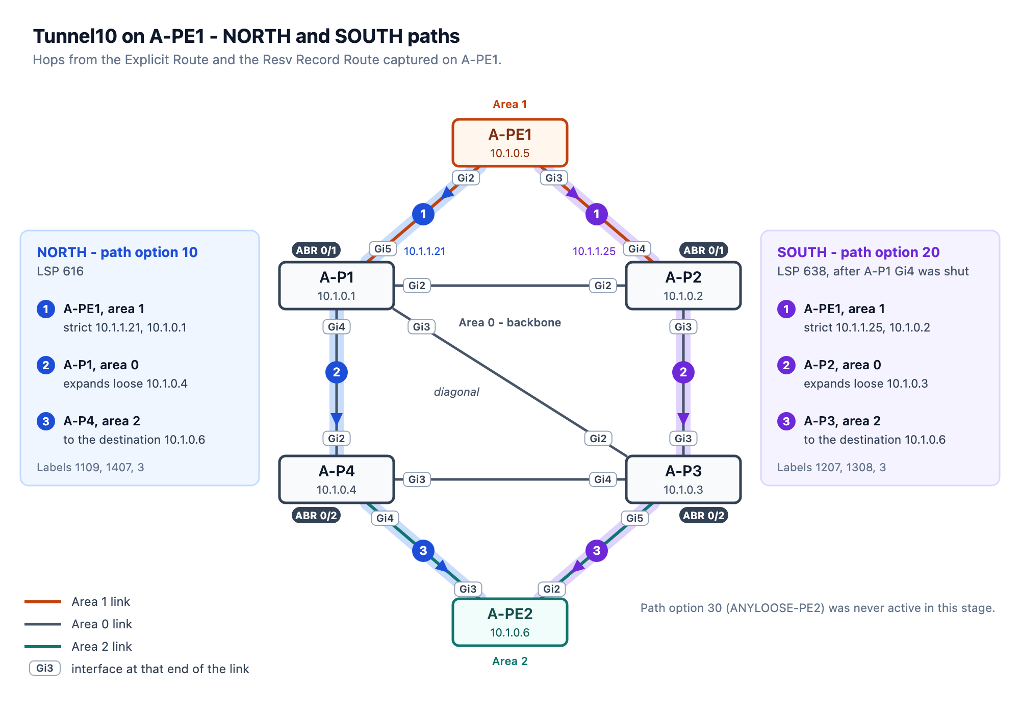
A-PE2 has the mirror image, Tunnel20 through A-P4 and A-P1.
The affinity line is in the configuration to show how an affinity looks in the outputs. It does not change any path in this topology.
Autoroute destination
autoroute announce, unsupported on an inter-area tunnel, adds the tunnel to the headend’s SPF as a link to the tail router, so the headend has to see the tail’s TE router ID in its own area. A-PE2 advertises its TE router ID, 10.1.0.6, in area 2 only. tunnel mpls traffic-eng autoroute destination installs a static route for the tunnel destination through the tunnel instead:
A-PE1#show ip route 10.1.0.6
Routing entry for 10.1.0.6/32
  Known via "static", distance 1, metric 0 (connected)
  Routing Descriptor Blocks:
  * directly connected, via Tunnel10
      Route metric is 0, traffic share count is 1
It routes only 10.1.0.6/32. That is the BGP next hop of every VPN route A-PE2 advertises, so those routes resolve through Tunnel10.
Tunnel11 on the Diagonal
Tunnel11’s explicit path names A-P1 and A-P3 as loose hops:
ip explicit-path name DIAG-PE1-PE2
 next-address loose 10.1.0.1
 next-address loose 10.1.0.3
!
interface Tunnel11
 description TE to A-PE2 : explicit-path pinned to colored A-P1-A-P3 diagonal
 ip unnumbered Loopback0
 tunnel mode mpls traffic-eng
 tunnel destination 10.1.0.6
 tunnel mpls traffic-eng bandwidth 50000
 tunnel mpls traffic-eng path-option 10 explicit name DIAG-PE1-PE2
A-P1 computes the path between them. Every TE metric in area 0 is 1, so the diagonal, 10.1.1.16/30, costs 1 and the path through A-P2 or A-P4 costs 2. The Resv record route starts at 10.1.1.17, A-P1’s end of the diagonal:
A-PE1#show mpls traffic-eng tunnels tun 11

Name: TE to A-PE2 : explicit-path pinned to colored A-P1-A-P3 diagona (Tunnel11) Destination: 10.1.0.6
  Status:
    Admin: up         Oper: up     Path: valid       Signalling: connected
    path option 10, type explicit DIAG-PE1-PE2 (Basis for Setup, path weight 1)

  Config Parameters:
    Bandwidth: 50000    kbps (Global)  Priority: 7  7   Affinity: 0x0/0xFFFF
    Metric Type: TE (default)
    Path-selection Tiebreaker:
      Global: not set   Tunnel Specific: not set   Effective: min-fill (default)
    Hop Limit: disabled
    Cost Limit: disabled
    Path-invalidation timeout: 10000 msec (default), Action: Tear
    AutoRoute: disabled LockDown: disabled Loadshare: 50000 [40000] bw-based
    auto-bw: disabled
    Fault-OAM: disabled, Wrap-Protection: disabled, Wrap-Capable: No
  Active Path Option Parameters:
    State: explicit path option 10 is active
    BandwidthOverride: disabled  LockDown: disabled  Verbatim: disabled
  Node Hop Count: 1

  InLabel  :  -
  OutLabel : GigabitEthernet2, 1113
  Next Hop : 10.1.1.21
  RSVP Signalling Info:
       Src 10.1.0.5, Dst 10.1.0.6, Tun_Id 11, Tun_Instance 441
    RSVP Path Info:
      My Address: 10.1.1.22
      Explicit Route: 10.1.1.21 10.1.0.1 10.1.0.3*
      Record   Route:
      Tspec: ave rate=50000 kbits, burst=1000 bytes, peak rate=50000 kbits
    RSVP Resv Info:
      Record   Route:  10.1.1.17 10.1.1.29 10.1.1.30
On A-P1, Gi3 has 950000 of 1000000 kbps left at priority 7, after Tunnel11’s 50 Mbps:
  Link ID::  1 (GigabitEthernet3)
    Link Subnet Type:     Point-to-Point
    Link IP Address:      10.1.1.17
    Neighbor:             ID 10.1.0.3, IP 10.1.1.18
    TE metric:            1
    IGP metric:           1
    SRLGs:                None
    Physical Bandwidth:   1000000 kbits/sec
    Res. Global BW:       1000000 kbits/sec
    Res. Sub BW:          0 kbits/sec
    Downstream::
                                Global Pool   Sub Pool
                                -----------   ----------
      Reservable Bandwidth[0]:      1000000            0 kbits/sec
      Reservable Bandwidth[1]:      1000000            0 kbits/sec
      Reservable Bandwidth[2]:      1000000            0 kbits/sec
      Reservable Bandwidth[3]:      1000000            0 kbits/sec
      Reservable Bandwidth[4]:      1000000            0 kbits/sec
      Reservable Bandwidth[5]:      1000000            0 kbits/sec
      Reservable Bandwidth[6]:      1000000            0 kbits/sec
      Reservable Bandwidth[7]:       950000            0 kbits/sec
    Attribute Flags:      0x80000000
A-PE2’s Tunnel21 takes the diagonal in the other direction, from A-P3’s end.
The diagonal carries bit 31: mpls traffic-eng attribute-flags 0x80000000 on A-P1 Gi3 and A-P3 Gi2, the Attribute Flags line in the A-P1 output. An affinity of 0x80000000 mask 0x80000000 on Tunnel11 would require bit 31 on every link of the path, A-PE1’s own first hop included. Both of A-PE1’s area-1 uplinks advertise Affinity Bit : 0x0 in its show ip ospf mpls traffic-eng link output, so CSPF on A-PE1 finds no path. Tunnel11 uses an explicit path instead.
FRR at A-P1
A-P1 protects the NORTH path’s area-0 hop, A-P1 to A-P4 over Gi4, with two backup tunnels. Tunnel100 is the next-hop (NHOP) backup for the link: a strict path through A-P3 to A-P4, all inside area 0. Tunnel101 is the next-next-hop (NNHOP) backup for the node A-P4: loose through A-P3 to A-PE2, so it ends in area 2 and is an inter-area tunnel itself. Both are bound to Gi4:
ip explicit-path name BKP-LINK-P1P3P4
 next-address 10.1.0.3
 next-address 10.1.0.4
!
interface Tunnel100
 description FRR NHOP link-protect -> A-P4
 ip unnumbered Loopback0
 tunnel mode mpls traffic-eng
 tunnel destination 10.1.0.4
 tunnel mpls traffic-eng path-option 10 explicit name BKP-LINK-P1P3P4
!
ip explicit-path name BKP-NODE-VIA-P3
 next-address loose 10.1.0.3
 next-address loose 10.1.0.6
!
interface Tunnel101
 description FRR NNHOP node-protect -> A-PE2 (inter-area)
 ip unnumbered Loopback0
 tunnel mode mpls traffic-eng
 tunnel destination 10.1.0.6
 tunnel mpls traffic-eng path-option 10 explicit name BKP-NODE-VIA-P3
!
interface GigabitEthernet4
 mpls traffic-eng backup-path Tunnel100
 mpls traffic-eng backup-path Tunnel101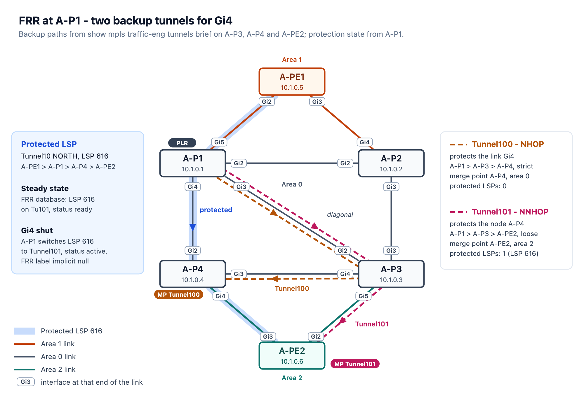
Neither backup has a backup-bw line, which leaves them at “any pool unlimited”: they protect an LSP from any bandwidth pool, with no bandwidth guarantee:
A-P1#show mpls traffic-eng tunnels backup
FRR NHOP link-protect -> A-P4
  LSP Head, Admin: up, Oper: up
  Tun ID: 100, LSP ID: 53, Source: 10.1.0.1
  Destination: 10.1.0.4
  Fast Reroute Backup Provided:
    Protected i/fs: Gi4
    Protected LSPs/Sub-LSPs: 0, Active: 0
    Backup BW: any pool unlimited; inuse: 0 kbps
    Backup flags: 0x0
FRR NNHOP node-protect -> A-PE2 (inter-area)
  LSP Head, Admin: up, Oper: up
  Tun ID: 101, LSP ID: 41, Source: 10.1.0.1
  Destination: 10.1.0.6
  Fast Reroute Backup Provided:
    Protected i/fs: Gi4
    Protected LSPs/Sub-LSPs: 1, Active: 0
    Backup BW: any pool unlimited; inuse: 100000 kbps
    Backup flags: 0x0
Tunnel10’s configuration carries fast-reroute node-protect. In the FRR database, A-P1 protects 10.1.0.5 10 [616], Tunnel10’s LSP from A-PE1, with Tunnel101, the NNHOP backup. Tunnel101’s label is implicit null. The merge point, A-PE2, is also the tail, and it signalled label 3 (10.1.0.6(3) in the opening capture):
A-P1#show mpls traffic-eng fast-reroute database
P2P Headend FRR information:
Protected tunnel               In-label Out intf/label   FRR intf/label   Status
---------------------------    -------- --------------   --------------   ------

P2P LSP midpoint frr information:
LSP identifier                 In-label Out intf/label   FRR intf/label   Status
---------------------------    -------- --------------   --------------   ------
10.1.0.5 10 [616]              1109     Gi4:1407         Tu101:implicit-n ready
Failover and Restore
I shut A-P1’s Gi4. A-P1 switched LSP 616 to Tunnel101:
A-P1#show mpls traffic-eng fast-reroute database detail
FRR Database Summary:
  Protected interfaces    : 1
  Protected LSPs/Sub-LSPs : 1
  Backup tunnels          : 2
  Active interfaces       : 1
  FRR Active tunnels      : 1

P2P LSPs:

 Tun ID: 10, LSP ID: 616, Source: 10.1.0.5
 Destination: 10.1.0.6
  State        : active
  InLabel      : 1109
  OutLabel     : Gi4:1407
  FRR OutLabel : Tu101:implicit-null

P2MP Sub-LSPs:
A-P1 then sent A-PE1 a PathErr, Notify: Tunnel locally repaired, and A-PE1 moved Tunnel10 to path option 20, SOUTH, as LSP 638 through A-P2 and A-P3:
A-PE1#show mpls traffic-eng tunn tun 10

Name: TE to A-PE2: NORTH primary / SOUTH secondary (Tunnel10) Destination: 10.1.0.6
  Status:
    Admin: up         Oper: up     Path: valid       Signalling: connected
    path option 20, type explicit SOUTH-PE1-PE2 (Basis for Setup, path weight 1)
    path option 10, type explicit NORTH-PE1-PE2
    path option 30, type explicit ANYLOOSE-PE2

  Config Parameters:
    Bandwidth: 100000   kbps (Global)  Priority: 7  7   Affinity: 0x0/0x80000000
    Metric Type: TE (default)
    Path-selection Tiebreaker:
      Global: not set   Tunnel Specific: not set   Effective: min-fill (default)
    Hop Limit: disabled
    Cost Limit: disabled
    Path-invalidation timeout: 10000 msec (default), Action: Tear
    AutoRoute: disabled LockDown: disabled Loadshare: 100000 [20000] bw-based
    AutoRoute destination: enabled
    auto-bw: disabled
    Fast Reroute: enabled, Node Protection: Yes, Bandwidth Protection: No
    Fault-OAM: disabled, Wrap-Protection: disabled, Wrap-Capable: No
  Active Path Option Parameters:
    State: explicit path option 20 is active
    BandwidthOverride: disabled  LockDown: disabled  Verbatim: disabled
  Node Hop Count: 1

  InLabel  :  -
  OutLabel : GigabitEthernet3, 1207
  Next Hop : 10.1.1.25
  RSVP Signalling Info:
       Src 10.1.0.5, Dst 10.1.0.6, Tun_Id 10, Tun_Instance 638
    RSVP Path Info:
      My Address: 10.1.1.26
      Explicit Route: 10.1.1.25 10.1.0.2 10.1.0.3*
      Record   Route:
      Tspec: ave rate=100000 kbits, burst=1000 bytes, peak rate=100000 kbits
    RSVP Resv Info:
      Record   Route:  10.1.0.2(1207) 10.1.1.5(1207)
                       10.1.0.3(1308) 10.1.1.29(1308)
                       10.1.0.6(3) 10.1.1.30(3)
      Fspec: ave rate=100000 kbits, burst=1000 bytes, peak rate=100000 kbits
  Shortest Unconstrained Path Info:
    Path Weight: UNKNOWN
    Explicit Route:  UNKNOWN

  History:
    Tunnel:
      Time since created: 22 hours, 27 minutes
      Time since path change: 1 minutes, 3 seconds
      Number of LSP IDs (Tun_Instances) used: 638
    Current LSP: [ID: 638]
      Uptime: 1 minutes, 6 seconds
      Selection: reoptimization
    Prior LSP: [ID: 616]
      ID: path option 10 [616]
      Removal Trigger: re-route path error
      Last Error: RSVP:: Path Error from 10.1.1.21: Notify: Tunnel locally repaired (flags 0)
A-PE1#show ip route 10.1.0.6
Routing entry for 10.1.0.6/32
  Known via "static", distance 1, metric 0 (connected)
  Routing Descriptor Blocks:
  * directly connected, via Tunnel10
      Route metric is 0, traffic share count is 1
The route that autoroute destination installed is tied to the Tunnel10 interface, so it did not change when the path under it did.
After no shutdown on Gi4 and a reoptimization on A-PE1, Tunnel10 went back to NORTH as LSP 639, with A-P1’s new label 1112:
  OutLabel : GigabitEthernet2, 1112
  Next Hop : 10.1.1.21
  RSVP Signalling Info:
       Src 10.1.0.5, Dst 10.1.0.6, Tun_Id 10, Tun_Instance 639
On A-P1, Tunnel101 protects the new LSP again, and A-P4’s label for it is 1409:
P2P LSP midpoint frr information:
LSP identifier                 In-label Out intf/label   FRR intf/label   Status
---------------------------    -------- --------------   --------------   ------
10.1.0.5 10 [639]              1112     Gi4:1409         Tu101:implicit-n ready
What’s Next
Adding RSVP-TE didn’t reset LDP on the same links. A-PE1’s two LDP sessions show 7w4d of uptime:
A-PE1#show mpls ldp neigh | i Up
        Up time: 7w4d
        Up time: 7w4d
The next stage adds SR-MPLS to three SP-A nodes and connects it to the LDP-only part of the network.


Leave a comment