During a migration from LDP to SR, or where some routers don’t support SR, part of the network runs SR and the rest runs only LDP. An SR node needs a prefix-SID for the destination, and an LDP-only router doesn’t advertise one for its loopback. A mapping server advertises prefix-SIDs on behalf of those routers. SR-capable node that also runs LDP swaps the SR label for its next hop’s LDP label, and the LSP continues into the LDP part of the network.
This stage adds SR-MPLS to three SP-A nodes: A-PE1, A-P1, and A-P2. The rest of the routers within SP-A, except A-RR, will stay configured as LDP only, and A-RR advertises prefix-SIDs for their loopbacks as a mapping server.
This is a traceroute from A-PE1 to 10.1.0.106, a second loopback on A-PE2, after the stage was configured:
A-PE1#traceroute 10.1.0.106 source lo0
Type escape sequence to abort.
Tracing the route to 10.1.0.106
VRF info: (vrf in name/id, vrf out name/id)
  1 10.1.1.21 [MPLS: Label 17606 Exp 0] 2 msec
    10.1.1.25 [MPLS: Label 17606 Exp 0] 2 msec
    10.1.1.21 [MPLS: Label 17606 Exp 0] 3 msec
  2 10.1.1.6 [MPLS: Label 1312 Exp 0] 2 msec
    10.1.1.18 [MPLS: Label 1312 Exp 0] 1 msec
    10.1.1.6 [MPLS: Label 1312 Exp 0] 2 msec
  3 10.1.1.30 2 msec 2 msec *
A-PE1 sends label 17606 to both uplinks, A-P1 (10.1.1.21) and A-P2 (10.1.1.25).
Hop 2 is A-P3 on both of its links, 10.1.1.18 on the diagonal from A-P1 and 10.1.1.6 from A-P2.
A-P3 receives 1312, its LDP label for 10.1.0.106, so A-P1 and A-P2 swapped the SR label for an LDP label.
A-P3 pops it, and A-PE2 (10.1.1.30) receives the packet without a label.
Topology file: topology.clab.yml · Addressing: ipam.md · Stage configs, 5 nodes (the three SR nodes, A-RR and A-PE2): stage_configs/lab02-s2-spa-sr-ldp/
The SR Nodes
A-PE1’s SR configuration:
segment-routing mpls
 global-block 17000 17999
 set-attributes
  address-family ipv4
   sr-label-preferred
  exit-address-family
 connected-prefix-sid-map
  address-family ipv4
   10.1.0.5/32 index 500 range 1
  exit-address-family
!
router ospf 1
 segment-routing area 1 mpls
 segment-routing mpls
The SRGB is 17000-17999 on every SP-A node that runs SR. The prefix-SID index is the node number times 100, so A-PE1’s index 500 is label 17500.
IOS-XE prefers the LDP label when a prefix has an LDP label and an SR label. sr-label-preferred makes A-PE1 impose the SR label. A-P1 and A-P2 have the same SR block without set-attributes, with indexes 100 and 200, and keep the LDP preference. A-P1 is an ABR between area 0 and area 1 and runs SR in both:
A-P1#show ip ospf segment-routing

            OSPF Router with ID (10.1.0.1) (Process ID 1)

Global segment-routing state: Enabled

Segment Routing enabled:
           Area    Topology name    Forwarding    Strict SPF
              0    Base             MPLS          Not capable
              1    Base             MPLS          Capable
    AS external    Base             MPLS          Not applicable

SR Attributes
    Prefer non-SR (LDP) Labels
    Do not advertise Explicit Null

Local MPLS label block (SRGB):
    Range: 17000 - 17999
    State: Created
The Mapping Server
A-RR, in area 0, runs the mapping server and doesn’t have assigned prefix-SID:
segment-routing
 global-block 17000 17999
 mapping-server
  prefix-sid-map
   address-family ipv4
    10.1.0.3/32 300 range 1
    10.1.0.4/32 400 range 1
    10.1.0.6/32 600 range 1
    10.1.0.106/32 606 range 1
    10.1.0.8/32 800 range 1
   !
  !
 !
!
router ospf 1
 segment-routing mpls
 segment-routing prefix-sid-map advertise-local
Each entry maps a loopback to an index: the four LDP-only nodes and A-PE2’s 10.1.0.106. IOS-XR takes the index without a keyword, whereas A-PE1’s connected-prefix-sid-map on IOS-XE uses index 500.
Under router ospf 1, segment-routing prefix-sid-map advertise-local makes A-RR’s OSPF advertise the map.
A-PE1 is in area 1, and its SID database lists the five mappings with M:
A-PE1#show ip ospf segment-routing sid-database

            OSPF Router with ID (10.1.0.5) (Process ID 1)

OSPF Segment Routing SIDs

Codes: L - local, N - label not programmed,
       M - mapping-server

SID             Prefix              Adv-Rtr-Id       Area-Id  Type      Algo
--------------  ------------------  ---------------  -------  --------  ----
100             10.1.0.1/32         10.1.0.1         1        Inter     0
                10.1.0.1/32         10.1.0.2         1        Inter     0
200             10.1.0.2/32         10.1.0.2         1        Inter     0
                10.1.0.2/32         10.1.0.1         1        Inter     0
300     (M)     10.1.0.3/32                                   Unknown   0
400     (M)     10.1.0.4/32                                   Unknown   0
500     (L)     10.1.0.5/32         10.1.0.5         1        Intra     0
600     (MN)    10.1.0.6/32                                   Unknown   0
606     (M)     10.1.0.106/32                                 Unknown   0
800     (M)     10.1.0.8/32                                   Unknown   0
100 and 200 are inter-area SIDs, and both ABRs advertise each of them into area 1. 600, the mapping for A-PE2’s Loopback0, 10.1.0.6, is MN: the label is not programmed. I have an explanation below of why I had to use a dedicated loopback on A-PE2 and configure a mapping for 10.1.0.106 next to the one for 10.1.0.6.
10.1.0.6 Stays on Tunnel10
In the previous stage, autoroute destination on Tunnel10 installed a static route to 10.1.0.6/32 through the tunnel, with distance 1. The SR label comes with the OSPF route for 10.1.0.6, but the static route wins over it. A-PE1 forwards 10.1.0.6 through Tunnel10:
A-PE1#show mpls forwarding-table 10.1.0.6
Local      Outgoing   Prefix           Bytes Label   Outgoing   Next Hop
Label      Label      or Tunnel Id     Switched      interface
1504  [T]  Pop Label  10.1.0.6/32      0             Tu10       point2point

[T]     Forwarding through a LSP tunnel.
        View additional labelling info with the 'detail' option
10.1.0.6 is the BGP next hop of every VPN route A-PE2 advertises, so sr-label-preferred has no impact on customer traffic. CustA traffic from HQ to Br1 leaves A-PE1 with two labels. The top label, 1112, is A-P1’s label for Tunnel10, and 1609 is the VPN label:
CustA-HQ#traceroute 10.10.0.2 source Loopback0 probe 1
Type escape sequence to abort.
Tracing the route to 10.10.0.2
VRF info: (vrf in name/id, vrf out name/id)
  1 10.1.10.1 1 msec
  2 10.1.1.21 [MPLS: Labels 1112/1609 Exp 0] 3 msec
  3 10.1.1.14 [MPLS: Labels 1409/1609 Exp 0] 2 msec
  4 10.1.10.5 [MPLS: Label 1609 Exp 0] 2 msec
  5 10.1.10.6 2 msec
The SR-to-LDP Swap on 10.1.0.106
To demonstrate the SR-to-LDP swap, I’ve added a second loopback, 10.1.0.106, on A-PE2, since A-PE2’s Loopback0 is already routed through Tunnel10 from the previous stage.
The interworking shows on A-P1 as a swap: an SR label comes in, and the next hop’s LDP label goes out. A directly connected neighbour advertises implicit-null in LDP for its own loopback, so A-P1 pops the label toward it.
To see the swap, the destination has to be at least two hops past A-P1.
A-P3, A-P4, and A-ASBR are A-P1’s neighbours, and A-PE2, behind A-P3 and A-P4, is the only LDP-only node two hops away. The second loopback is in area 2:
interface Loopback1
 ip address 10.1.0.106 255.255.255.255
 ipv6 address 2001:db8:1::106/128
 ip ospf 1 area 2
 ipv6 ospf 1 area 2
A-RR maps it to index 606, label 17606. In A-P1’s forwarding table, 17300, 17400 and 17800 pop, and 17606 swaps to 1407, A-P4’s LDP label, or 1312, A-P3’s:
17200      Pop Label  10.1.0.2/32      0             Gi2        10.1.1.2
17300 [M]  Pop Label  10.1.0.3/32      8205686       Gi3        10.1.1.18
17400 [M]  Pop Label  10.1.0.4/32      2090112       Gi4        10.1.1.14
17500      Pop Label  10.1.0.5/32      0             Gi5        10.1.1.22
17600 [M]  1404       10.1.0.6/32      0             Gi4        10.1.1.14
      [M]  1304       10.1.0.6/32      10618         Gi3        10.1.1.18
17606 [M]  1407       10.1.0.106/32    0             Gi4        10.1.1.14
      [M]  1312       10.1.0.106/32    728           Gi3        10.1.1.18
17800 [M] Pop Label 10.1.0.8/32 60106681 Gi7 10.1.1.42 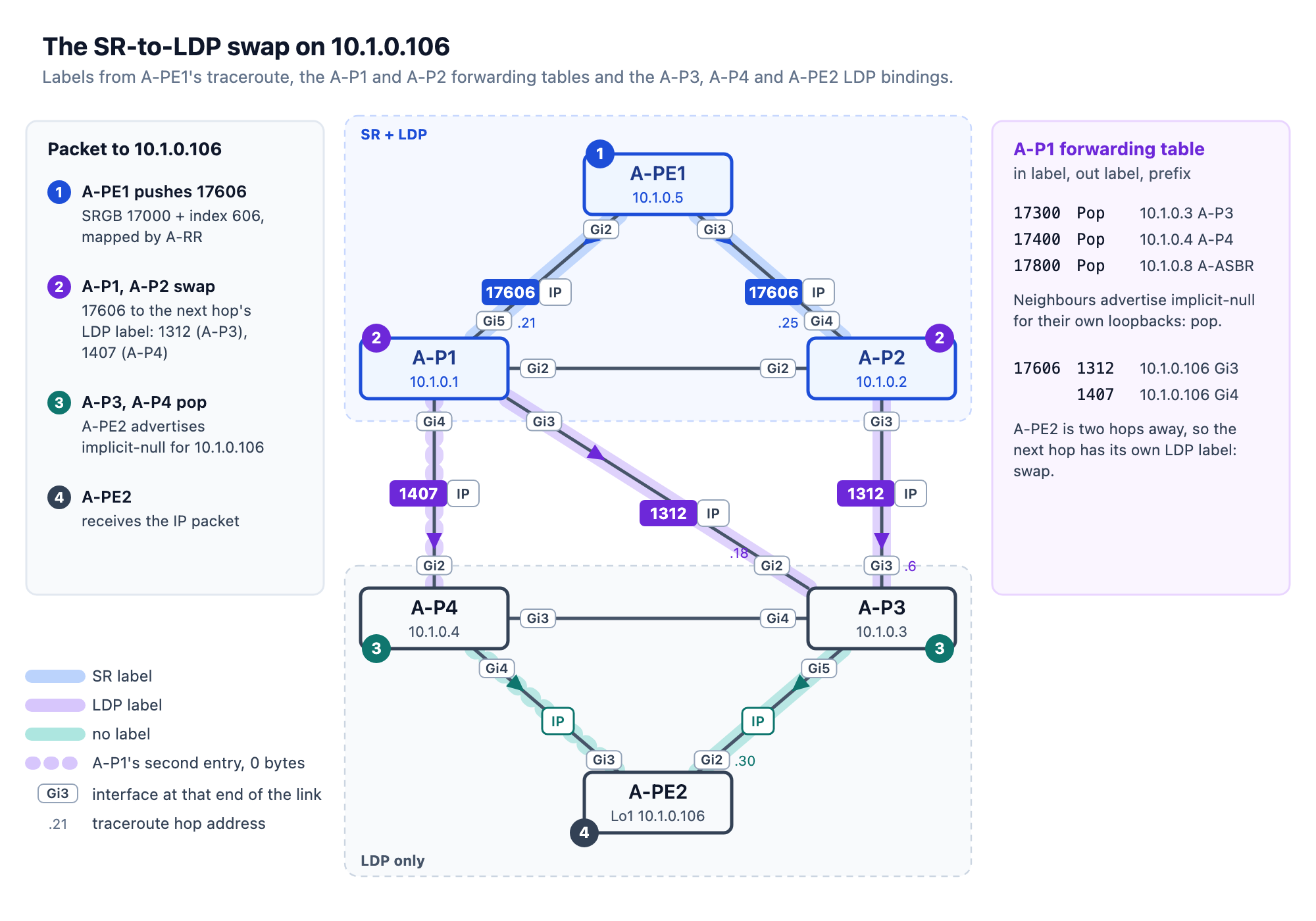
A-P1 doesn’t require any specific configuration for the swap: it runs SR and LDP, and its next hops toward A-PE2 run LDP only.
What’s Next
Adding SR didn’t reset LDP. A-PE1’s two LDP sessions show 8w0d of uptime:
A-PE1#show mpls ldp neighbor | include Up
        Up time: 8w0d
        Up time: 8w0d
The next stage builds an LDP-signalled VPWS between CustB-Hub on A-PE1 and CustB-Spk1 on A-PE2.


Leave a comment