PIM sparse mode builds a multicast tree only where receivers ask for it. A receiver’s router joins a shared tree toward the rendezvous point (RP). The first-hop router of a new source registers the source with the RP, and after the first packets, the receiver’s router joins a tree rooted at the source. In the reverse path forwarding (RPF) check, a router accepts a multicast packet only on the interface it would use to reach the packet’s source, and it takes that interface from the unicast routing table.
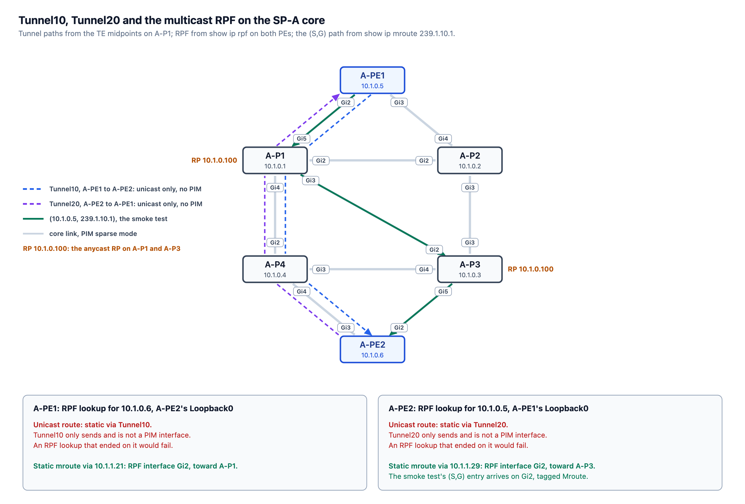
In SP-A, PIM sparse mode runs in the global table on the links between the P routers and on the PE uplinks. A-P1 and A-P3 share the RP address 10.1.0.100 and exchange active sources over MSDP. On A-PE1, the unicast route and the multicast RPF for A-PE2’s Loopback0 point to different interfaces:
A-PE1#show ip rpf 10.1.0.6
RPF information for ? (10.1.0.6)
  RPF interface: GigabitEthernet2
  RPF neighbor: ? (10.1.1.21)
  RPF route/mask: 10.1.0.6/32
  RPF type: multicast (static)
  Doing distance-preferred lookups across tables
  RPF topology: ipv4 multicast base
A-PE1#show ip route 10.1.0.6
Routing entry for 10.1.0.6/32
  Known via "static", distance 1, metric 0 (connected)
  Routing Descriptor Blocks:
  * directly connected, via Tunnel10
      Route metric is 0, traffic share count is 1
The unicast route is the static that autoroute destination installed for Tunnel10 in Inter-Area MPLS-TE on SP-A. Tunnel10 carries traffic one way, from A-PE1 to A-PE2. Multicast from 10.1.0.6 reaches A-PE1 on the physical uplinks, so an RPF check that followed the unicast route would fail, and A-PE1 would drop it. Instead, a static multicast route resolves the RPF lookup for 10.1.0.6 to Gi2, toward A-P1.
Topology file: topology.clab.yml · Addressing: ipam.md · Stage configs, 6 nodes (four P routers, two PEs): stage_configs/lab02-s4-spa-multicast/
PIM-SM and the Anycast RP on A-P1
The whole configuration of A-P1 for this stage:
ip multicast-routing distributed
!
interface Loopback1
 description ANYCAST-RP (shared with A-P3) -- 10.1.0.100
 ip address 10.1.0.100 255.255.255.255
 ip ospf 1 area 0
!
interface GigabitEthernet2
 ip pim sparse-mode
interface GigabitEthernet3
 ip pim sparse-mode
interface GigabitEthernet4
 ip pim sparse-mode
interface GigabitEthernet5
 ip pim sparse-mode
!
ip pim ssm default
ip pim rp-address 10.1.0.100
!
ip msdp peer 10.1.0.3 connect-source Loopback0
ip msdp originator-id Loopback0
ip msdp cache-sa-state
ip pim sparse-mode enables PIM on Gi2 to A-P2, Gi3 to A-P3, Gi4 to A-P4 and Gi5 to A-PE1. Gi6 to A-RR and Gi7 to A-ASBR have no PIM: A-RR is an XRd control-plane node with no data plane, and A-ASBR is not on the path between A-PE1 and A-PE2.
Loopback1 advertises 10.1.0.100/32 into OSPF area 0, and A-P3 has the same Loopback1 configured for the anycast. A-P1 to A-P4, A-PE1, and A-PE2 all have ip pim rp-address 10.1.0.100, and each of them uses the closest RP. The closest RP is determined by the OSPF cost to 10.1.0.100.
A source registers with the RP closest to its first-hop router, and a receiver joins the RP closest to its own router, so the two RPs have to tell each other about active sources. MSDP does that with Source-Active (SA) messages; PIM Anycast-RP (RFC 4610) does it by forwarding Register messages between the RPs. This lab uses MSDP because the blueprint lists anycast RP and MSDP together.
The MSDP session runs between the Loopback0 addresses, 10.1.0.1 on A-P1 and 10.1.0.3 on A-P3, because each RP owns 10.1.0.100 itself. An SA carries the source, the group, and the address of the RP that originated it. ip msdp originator-id Loopback0 sets that address to A-P1’s Loopback0, 10.1.0.1. The SA reaches A-P3 from 10.1.0.1, and IOS accepts an SA that comes directly from its originating RP without an RPF check. The session on A-P1:
A-P1#show ip msdp summary
MSDP Peer Status Summary
Peer Address     AS    State    Uptime/  Reset SA    Peer Name
                                Downtime Count Count
10.1.0.3         ?     Up       00:22:46 0     0     ?
A-P1#show ip msdp peer 10.1.0.3
MSDP Peer 10.1.0.3 (?), AS ?
  Connection status:
    State: Up, Resets: 0, Connection source: Loopback0 (10.1.0.1)
    Uptime(Downtime): 00:22:58, Messages sent/received: 23/23
    Output messages discarded: 0
    Connection and counters cleared 00:25:58 ago
The Static Mroute on A-PE1 and A-PE2
The whole configuration of A-PE1 for this stage:
ip multicast-routing distributed
!
interface GigabitEthernet2
 ip pim sparse-mode
interface GigabitEthernet3
 ip pim sparse-mode
!
ip pim ssm default
ip pim rp-address 10.1.0.100
!
ip mroute 10.1.0.6 255.255.255.255 10.1.1.21
A-PE1 runs PIM on its two uplinks, Gi2 to A-P1 and Gi3 to A-P2:
A-PE1#show ip pim interface

Address          Interface                Ver/   Nbr    Query  DR         DR
                                          Mode   Count  Intvl  Prior
10.1.1.22        GigabitEthernet2         v2/S   1      30     1          10.1.1.22
10.1.1.26        GigabitEthernet3         v2/S   1      30     1          10.1.1.26
Tunnel10 is not on that list. The tunnel exists only on A-PE1, and A-PE1 can only send into it. Its packets arrive at A-PE2 on an ordinary physical interface. Nothing ever comes in on Tunnel10, and there is no PIM neighbor at its far end. An RPF lookup for 10.1.0.6 that ended on Tunnel10 would leave A-PE1 with no interface to accept A-PE2’s multicast on, and no neighbor to send its PIM Join to:
mpls traffic-eng multicast-intact under the IGP keeps the IGP paths for the RPF lookup, but only for tunnels with autoroute announce. The route from autoroute destination is a static route, and that command does not cover it.
ip mroute 10.1.0.6 255.255.255.255 10.1.1.21 gives the RPF lookup its own route to A-PE2’s Loopback0, through A-P1:
A-PE1#show ip mroute static
Mroute: 10.1.0.6/32, RPF neighbor: 10.1.1.21, distance: 1
The unicast route stays on Tunnel10, so the L3VPN, VPWS and EVPN services keep using the tunnel. A-PE2 has the mirror configuration: its static mroute sends the RPF lookup for A-PE1’s 10.1.0.5 to A-P3 at 10.1.1.29, while the unicast route uses Tunnel20, A-PE2’s own RSVP-TE tunnel to A-PE1:
A-PE2#show ip rpf 10.1.0.5
RPF information for ? (10.1.0.5)
  RPF interface: GigabitEthernet2
  RPF neighbor: ? (10.1.1.29)
  RPF route/mask: 10.1.0.5/32
  RPF type: multicast (static)
  Doing distance-preferred lookups across tables
  RPF topology: ipv4 multicast base
A-PE2#show ip route 10.1.0.5
Routing entry for 10.1.0.5/32
  Known via "static", distance 1, metric 0 (connected)
  Routing Descriptor Blocks:
  * directly connected, via Tunnel20
      Route metric is 0, traffic share count is 1
A-PE2#show ip mroute static
Mroute: 10.1.0.5/32, RPF neighbor: 10.1.1.29, distance: 1
The Smoke Test with Group 239.1.10.1
The test needs configuration that is not in the stage configs. It was added to the two PE loopbacks only for the test and removed after the captures. On A-PE1:
interface Loopback0
 ip pim sparse-mode
On A-PE2:
interface Loopback0
 ip pim sparse-mode
 ip igmp join-group 239.1.10.1
With PIM on its Loopback0, A-PE1 registers 10.1.0.5 as a source with the RP. ip igmp join-group makes A-PE2 a member of the group, so it joins the shared tree and answers a ping sent to 239.1.10.1. The next stage adds ip pim sparse-mode to both Loopback0s as permanent configuration.
The ping from A-PE1’s Loopback0:
A-PE1#ping 239.1.10.1 source lo0 repeat 5
Type escape sequence to abort.
Sending 5, 100-byte ICMP Echos to 239.1.10.1, timeout is 2 seconds:
Packet sent with a source address of 10.1.0.5

Reply to request 0 from 10.1.0.6, 4 ms
Reply to request 1 from 10.1.0.6, 4 ms
Reply to request 1 from 10.1.0.6, 34 ms
Reply to request 1 from 10.1.0.6, 30 ms
Reply to request 1 from 10.1.0.6, 11 ms
Reply to request 2 from 10.1.0.6, 3 ms
Reply to request 2 from 10.1.0.6, 3 ms
Reply to request 2 from 10.1.0.6, 3 ms
Reply to request 3 from 10.1.0.6, 3 ms
Reply to request 3 from 10.1.0.6, 3 ms
Reply to request 3 from 10.1.0.6, 3 ms
Reply to request 4 from 10.1.0.6, 3 ms
Reply to request 4 from 10.1.0.6, 3 ms
Reply to request 4 from 10.1.0.6, 3 ms
Unless the extended ping names an interface, IOS sends each request out of every PIM interface on the router. A-PE1 has three: Loopback0, Gi2 and Gi3, so most requests reached A-PE2 three times. A re-run with the same three PIM interfaces on A-PE1 and the extended ping set to Loopback0, showed one reply per request:
A-PE1#ping ip
Target IP address: 239.1.10.1
Repeat count [1]: 5
Datagram size [100]:
Timeout in seconds [2]:
Extended commands [n]: y
Interface [All]: Loopback0
Time to live [255]:
Ingress ping [n]:
Source address or interface: Loopback0
DSCP Value [0]:
Type of service [0]:
Set DF bit in IP header? [no]:
Validate reply data? [no]:
Data pattern [0x0000ABCD]:
Loose, Strict, Record, Timestamp, Verbose[none]:
Sweep range of sizes [n]:
Type escape sequence to abort.
Sending 5, 100-byte ICMP Echos to 239.1.10.1, timeout is 2 seconds:
Packet sent with a source address of 10.1.0.5

Reply to request 0 from 10.1.0.6, 4 ms
Reply to request 1 from 10.1.0.6, 3 ms
Reply to request 2 from 10.1.0.6, 3 ms
Reply to request 3 from 10.1.0.6, 5 ms
Reply to request 4 from 10.1.0.6, 3 ms
A-PE1#
On A-PE1, the first-hop router:
A-PE1#show ip mroute 239.1.10.1
IP Multicast Routing Table
Flags: D - Dense, S - Sparse, B - Bidir Group, s - SSM Group, C - Connected,
       L - Local, P - Pruned, R - RP-bit set, F - Register flag,
       T - SPT-bit set, J - Join SPT, M - MSDP created entry, E - Extranet,
       X - Proxy Join Timer Running, A - Candidate for MSDP Advertisement,
       U - URD, I - Received Source Specific Host Report,
       Z - Multicast Tunnel, z - MDT-data group sender,
       Y - Joined MDT-data group, y - Sending to MDT-data group,
       G - Received BGP C-Mroute, g - Sent BGP C-Mroute,
       N - Received BGP Shared-Tree Prune, n - BGP C-Mroute suppressed,
       Q - Received BGP S-A Route, q - Sent BGP S-A Route,
       V - RD & Vector, v - Vector, p - PIM Joins on route,
       x - VxLAN group, c - PFP-SA cache created entry
Outgoing interface flags: H - Hardware switched, A - Assert winner, p - PIM Join
 Timers: Uptime/Expires
 Interface state: Interface, Next-Hop or VCD, State/Mode

(*, 239.1.10.1), 00:00:16/stopped, RP 10.1.0.100, flags: SPF
  Incoming interface: GigabitEthernet2, RPF nbr 10.1.1.21
  Outgoing interface list: Null

(10.1.0.5, 239.1.10.1), 00:00:16/00:03:21, flags: FT
  Incoming interface: Loopback0, RPF nbr 0.0.0.0
  Outgoing interface list:
    GigabitEthernet2, Forward/Sparse, 00:00:16/00:03:15, A
F and T on the (S,G) entry mark A-PE1 as the router that registers the source and sends its traffic on the source tree, out Gi2. The (*,G) entry reaches the RP through A-P1 (10.1.1.21) by OSPF. The RP address is not a tunnel destination, so it needs no static mroute.
On A-P1, show ip mroute 239.1.10.1 has these two entries:
(*, 239.1.10.1), 00:00:42/stopped, RP 10.1.0.100, flags: SP
  Incoming interface: Null, RPF nbr 0.0.0.0
  Outgoing interface list: Null

(10.1.0.5, 239.1.10.1), 00:00:42/00:02:49, flags: TA
  Incoming interface: GigabitEthernet5, RPF nbr 10.1.1.22
  Outgoing interface list:
    GigabitEthernet3, Forward/Sparse, 00:00:42/00:02:47
The source arrives on Gi5 from A-PE1 and leaves on Gi3, the diagonal to A-P3. The A flag marks the entry that A-P1 advertises to A-P3 in an SA. The (*,G) entry has no outgoing interface, because A-PE2 joined the shared tree at A-P3, the RP closer to it.
A-P3’s SA cache holds the source with A-P1’s Loopback0 as both the RP and the peer:
A-P3#show ip msdp sa-cache
MSDP Source-Active Cache - 1 entries
(10.1.0.5, 239.1.10.1), RP 10.1.0.1, AS ?,00:01:00/00:05:53, Peer 10.1.0.1
On A-PE2, the last-hop router, show ip mroute 239.1.10.1 has these two entries:
(*, 239.1.10.1), 00:00:48/stopped, RP 10.1.0.100, flags: SJCL
  Incoming interface: GigabitEthernet2, RPF nbr 10.1.1.29
  Outgoing interface list:
    Loopback0, Forward/Sparse, 00:00:48/00:02:11

(10.1.0.5, 239.1.10.1), 00:00:28/00:02:31, flags: LJT
  Incoming interface: GigabitEthernet2, RPF nbr 10.1.1.29, Mroute
  Outgoing interface list:
    Loopback0, Forward/Sparse, 00:00:28/00:02:31
Mroute after the RPF neighbor of the (S,G) entry means the RPF came from the static mroute, which points at A-P3 over Gi2. J (Join SPT) on both entries means A-PE2 moved from the shared tree to the source tree after the first packets.
What’s Next
The CustA L3VPN between HQ and Br1 still works over IPv4 and IPv6 after the stage:
CustA-HQ#ping 10.10.0.2 source lo0
Type escape sequence to abort.
Sending 5, 100-byte ICMP Echos to 10.10.0.2, timeout is 2 seconds:
Packet sent with a source address of 10.10.0.1
!!!!!
Success rate is 100 percent (5/5), round-trip min/avg/max = 2/2/3 ms
CustA-HQ#ping 2001:db8:10::2 source lo0
Type escape sequence to abort.
Sending 5, 100-byte ICMP Echos to 2001:DB8:10::2, timeout is 2 seconds:
Packet sent with a source address of 2001:DB8:10::1
!!!!!
Success rate is 100 percent (5/5), round-trip min/avg/max = 1/4/16 ms
CustA-HQ#
The next stage builds mVPN Profile 0 for CustA on this core.


Leave a Reply