A multicast VPN carries a customer’s multicast across the provider core. In draft-Rosen mVPN, also called Profile 0, that multicast travels on multicast distribution trees (MDTs) between the PEs of the VRF. The default MDT is always up and connects every PE of the VRF. A data MDT is an extra tree for a single high-rate customer flow, and only the PEs with receivers for that flow join it.
Each MDT is one provider multicast group that the PEs join. The PE sends the customer’s multicast traffic and PIM messages to the default MDT group inside GRE, with its own loopback as the source. The PEs of the VRF become PIM neighbors over that group, as if they shared one LAN. A customer flow above a rate threshold moves to a data MDT group of its own.
In SP-A, the CustA VRF runs on A-PE1, toward CustA-HQ, and on A-PE2, toward CustA-Br1. The default MDT is 239.1.10.1, an ASM group served by the anycast RP 10.1.0.100 from the previous post. Inside the VRF, CustA elects its own RP with Auto-RP.
A-PE1 and A-PE2 connect only through the P routers, and A-PE1 lists A-PE2’s Loopback0, 10.1.0.6, as a PIM neighbor on Tunnel1:
A-PE1#show ip pim vrf CustA neigh
PIM Neighbor Table
Mode: B - Bidir Capable, DR - Designated Router, N - Default DR Priority,
      P - Proxy Capable, S - State Refresh Capable, G - GenID Capable,
      L - DR Load-balancing Capable
Neighbor          Interface                Uptime/Expires    Ver   DR
Address                                                            Prio/Mode
10.1.0.6          Tunnel1                  2d08h/00:01:38    v2    1 / DR S P G
10.1.10.2         GigabitEthernet4         2d08h/00:01:38    v2    1 / DR S P G
The second neighbor, 10.1.10.2 on Gi4, is CustA-HQ.
Topology file: topology.clab.yml · Addressing: ipam.md · Stage configs, 5 nodes (two PEs, the route reflector, two CustA CEs): stage_configs/lab02-s5-spa-mvpn-p0/
The PE Configuration
The whole configuration of A-PE1 for this stage:
ip multicast-routing vrf CustA distributed
!
vrf definition CustA
 address-family ipv4
  mdt default 239.1.10.1
  mdt data 232.1.10.0 0.0.0.255 threshold 1
 exit-address-family
!
interface Loopback0
 ip pim sparse-mode
!
interface GigabitEthernet4
 ip pim sparse-mode
!
ip pim vrf CustA autorp listener
!
router bgp 64501
 address-family ipv4 mdt
  neighbor 10.1.0.7 activate
 exit-address-family
!
ip multicast-routing vrf CustA distributed enables multicast routing in the VRF. Under the VRF’s IPv4 address family, mdt default sets the default MDT group, and mdt data sets the data MDT pool and the switchover threshold. In my case, it is 1 kbps, since I don’t have a real traffic generator. Loopback0 is the source of the PE’s MDT traffic, so it runs PIM, and the PE joins the default MDT group on it. Gi4 runs PIM in the VRF toward CustA-HQ. A-PE2 has the same configuration, with Gi4 toward CustA-Br1.
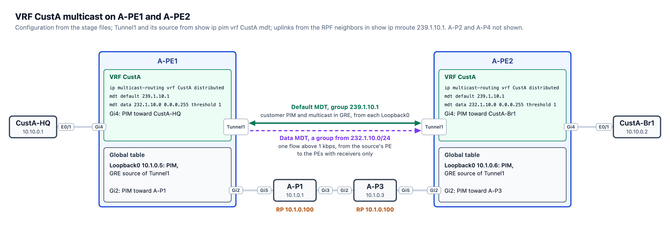
IOS-XE builds Tunnel1 for the default MDT, with Loopback0 as the source. This tunnel was displayed in the first output with PIM neighbors within vrf CustA:
A-PE1#show ip pim vrf CustA mdt
  * implies mdt is the default MDT, # is (*,*) Wildcard,
  > is non-(*,*) Wildcard
  MDT Group/Num   Interface   Source                   VRF
* 239.1.10.1      Tunnel1     Loopback0                CustA
The Default MDT in the Global Table
A-PE2’s entries for the default MDT group:
A-PE2#show ip mroute 239.1.10.1
IP Multicast Routing Table
Flags: D - Dense, S - Sparse, B - Bidir Group, s - SSM Group, C - Connected,
       L - Local, P - Pruned, R - RP-bit set, F - Register flag,
       T - SPT-bit set, J - Join SPT, M - MSDP created entry, E - Extranet,
       X - Proxy Join Timer Running, A - Candidate for MSDP Advertisement,
       U - URD, I - Received Source Specific Host Report,
       Z - Multicast Tunnel, z - MDT-data group sender,
       Y - Joined MDT-data group, y - Sending to MDT-data group,
       G - Received BGP C-Mroute, g - Sent BGP C-Mroute,
       N - Received BGP Shared-Tree Prune, n - BGP C-Mroute suppressed,
       Q - Received BGP S-A Route, q - Sent BGP S-A Route,
       V - RD & Vector, v - Vector, p - PIM Joins on route,
       x - VxLAN group, c - PFP-SA cache created entry
Outgoing interface flags: H - Hardware switched, A - Assert winner, p - PIM Join
 Timers: Uptime/Expires
 Interface state: Interface, Next-Hop or VCD, State/Mode

(*, 239.1.10.1), 2d08h/stopped, RP 10.1.0.100, flags: SJCFZ
  Incoming interface: GigabitEthernet2, RPF nbr 10.1.1.29
  Outgoing interface list:
    MVRF CustA, Forward/Sparse, 2d08h/00:02:06

(10.1.0.5, 239.1.10.1), 2d08h/00:01:23, flags: JTZ
  Incoming interface: GigabitEthernet2, RPF nbr 10.1.1.29, Mroute
  Outgoing interface list:
    MVRF CustA, Forward/Sparse, 2d08h/00:02:08

(10.1.0.6, 239.1.10.1), 2d08h/00:03:02, flags: FT
  Incoming interface: Loopback0, RPF nbr 0.0.0.0
  Outgoing interface list:
    GigabitEthernet2, Forward/Sparse, 1d23h/00:03:01
Each PE sends to the default MDT group and receives from it, so A-PE2 has an entry for each direction.
(10.1.0.6, 239.1.10.1) is A-PE2 sending. The source is its own Loopback0, and the GRE packets leave on Gi2 toward A-P3.
(10.1.0.5, 239.1.10.1) is A-PE2 receiving from A-PE1. The packets arrive on Gi2 from A-P3. The outgoing interface MVRF CustA means that A-PE2 removes the GRE header and passes the inner packet to the CustA VRF, where it arrives on Tunnel1. The (*, 239.1.10.1) entry delivers to the VRF the same way, through the RP 10.1.0.100. Its C flag comes from the PE joining the group on its own Loopback0. Z (Multicast Tunnel) marks the two entries that deliver into the VRF.
Mroute after the RPF neighbor of A-PE1’s entry means that the RPF lookup for 10.1.0.5 used the static mroute from the previous post, which points to Gi2, toward A-P3 at 10.1.1.29.
BGP IPv4 MDT on A-RR
The BGP IPv4 MDT address family carries each PE’s route distinguisher, Loopback0 and default MDT group. With an ASM default MDT, the PEs find each other through PIM without it. With an SSM default MDT, the BGP update is how a PE learns which sources to join.
A-RR reflects the IPv4 MDT routes between the two PEs:
router bgp 64501
 address-family ipv4 mdt
 !
 neighbor 10.1.0.5
  address-family ipv4 mdt
   route-reflector-client
 !
 neighbor 10.1.0.6
  address-family ipv4 mdt
   route-reflector-client
!
On A-PE1, PIM reads A-PE2’s entry as an MDT peer learned from A-RR, 10.1.0.7:
A-PE1#show bgp ipv4 mdt al
BGP table version is 11, local router ID is 10.1.0.5
Status codes: s suppressed, d damped, h history, * valid, > best, i - internal,
              r RIB-failure, S Stale, m multipath, b backup-path, f RT-Filter,
              x best-external, a additional-path, c RIB-compressed,
              t secondary path, L long-lived-stale,
Origin codes: i - IGP, e - EGP, ? - incomplete
RPKI validation codes: V valid, I invalid, N Not found

     Network          Next Hop            Metric LocPrf Weight Path
Route Distinguisher: 10.1.0.5:10 (default for vrf CustA)
 *>   10.1.0.5/32      0.0.0.0                                0 ?
Route Distinguisher: 10.1.0.6:10
 *>i  10.1.0.6/32      10.1.0.6                 0    100      0 ?
A-PE1#show ip pim mdt bgp
MDT (Route Distinguisher + IPv4)               Router ID         Next Hop
  MDT group 239.1.10.1
   10.1.0.5:10:10.1.0.6                        10.1.0.7          10.1.0.6
Activating a new address family on an existing BGP session resets the session, which also affects every other address family on it. On A-RR, show bgp ipv4 mdt neighbors 10.1.0.5 lists four address families on the session to A-PE1:
  Neighbor capabilities:
    Route refresh: advertised (old + new) and received (old + new)
    4-byte AS: advertised and received
    Address family VPNv4 Unicast: advertised and received
    Address family VPNv6 Unicast: advertised and received
    Address family IPv4 MDT: advertised and received
    Address family L2VPN EVPN: advertised and received
The end of the same output gives the reason for the last reset:
  Connections established 5; dropped 4
  Local host: 10.1.0.7, Local port: 179, IF Handle: 0x00000000
  Foreign host: 10.1.0.5, Foreign port: 35572
  Last reset 2d08h, due to Address family activated
The CustA L3VPN between HQ and Br1 works over IPv4 and IPv6 after the reset:
CustA-HQ#ping 10.10.0.2 source lo0
Type escape sequence to abort.
Sending 5, 100-byte ICMP Echos to 10.10.0.2, timeout is 2 seconds:
Packet sent with a source address of 10.10.0.1
!!!!!
Success rate is 100 percent (5/5), round-trip min/avg/max = 2/2/3 ms
CustA-HQ#ping 2001:db8:10::2 source lo0
Type escape sequence to abort.
Sending 5, 100-byte ICMP Echos to 2001:DB8:10::2, timeout is 2 seconds:
Packet sent with a source address of 2001:DB8:10::1
!!!!!
Success rate is 100 percent (5/5), round-trip min/avg/max = 1/3/10 ms
Customer Auto-RP over the Default MDT
With Auto-RP, a candidate RP announces itself to 224.0.1.39. A mapping agent listens to that group, elects the RP, and sends the result to 224.0.1.40. Routers need those two groups before they know any RP, so ip pim autorp listener floods them in dense mode over sparse-mode interfaces.
CustA-HQ is the candidate RP:
ip multicast-routing
!
ip pim autorp listener
!
interface Loopback0
 ip pim sparse-mode
!
interface Ethernet0/1
 ip pim sparse-mode
!
ip pim send-rp-announce Loopback0 scope 16
!
CustA-Br1 is the mapping agent:
ip multicast-routing
!
ip pim autorp listener
!
interface Loopback0
 ip pim sparse-mode
!
interface Ethernet0/1
 ip pim sparse-mode
!
ip pim send-rp-discovery Loopback0 scope 16
!
On both PEs, ip pim vrf CustA autorp listener applies the listener to the CustA VRF. CustA-HQ is attached to A-PE1 and CustA-Br1 to A-PE2, so each message has to cross the default MDT. On Br1, the info source of the mapping is the candidate RP itself, CustA-HQ:
CustA-Br1#show ip pim rp mapping in-use
PIM Group-to-RP Mappings
This system is an RP-mapping agent (Loopback0)

Group(s) 224.0.0.0/4
  RP 10.10.0.1 (?), v2v1
    Info source: 10.10.0.1 (?), elected via Auto-RP
         Uptime: 2d08h, expires: 00:02:22

Dynamic (Auto-RP or BSR) RPs in cache that are in use:
Group(s): 224.0.0.0/4, RP: 10.10.0.1, expires: 00:00:55
A-PE1 learned the same mapping from the mapping agent, CustA-Br1 at 10.10.0.2:
A-PE1#show ip pim vrf CustA rp mapping
PIM Group-to-RP Mappings

Group(s) 224.0.0.0/4
  RP 10.10.0.1 (?), v2v1
    Info source: 10.10.0.2 (?), elected via Auto-RP
         Uptime: 1d23h, expires: 00:02:55
Customer Traffic and the Data MDT
The test needs configuration that is not in the stage configs. ip igmp join-group 239.10.10.10 on CustA-Br1’s Loopback0 makes Br1 a member of the group, so it answers a ping sent to that group:
CustA-Br1#show run interface Loopback0
Building configuration...

Current configuration : 189 bytes
!
interface Loopback0
 ip address 10.10.0.2 255.255.255.255
 ip pim sparse-mode
 ip igmp join-group 239.10.10.10
 ip ospf 1 area 0
 ipv6 address 2001:DB8:10::2/128
 ipv6 ospf 1 area 0
end
The ping from CustA-HQ’s Loopback0, the first three of 20 requests:
CustA-HQ#ping 239.10.10.10 source Loopback0 repeat 20
Type escape sequence to abort.
Sending 20, 100-byte ICMP Echos to 239.10.10.10, timeout is 2 seconds:
Packet sent with a source address of 10.10.0.1

Reply to request 0 from 10.10.0.2, 17 ms
Reply to request 0 from 10.10.0.2, 27 ms
Reply to request 1 from 10.10.0.2, 4 ms
Reply to request 1 from 10.10.0.2, 4 ms
Reply to request 2 from 10.10.0.2, 4 ms
Reply to request 2 from 10.10.0.2, 4 ms
Each of the 20 requests drew two replies from 10.10.0.2.
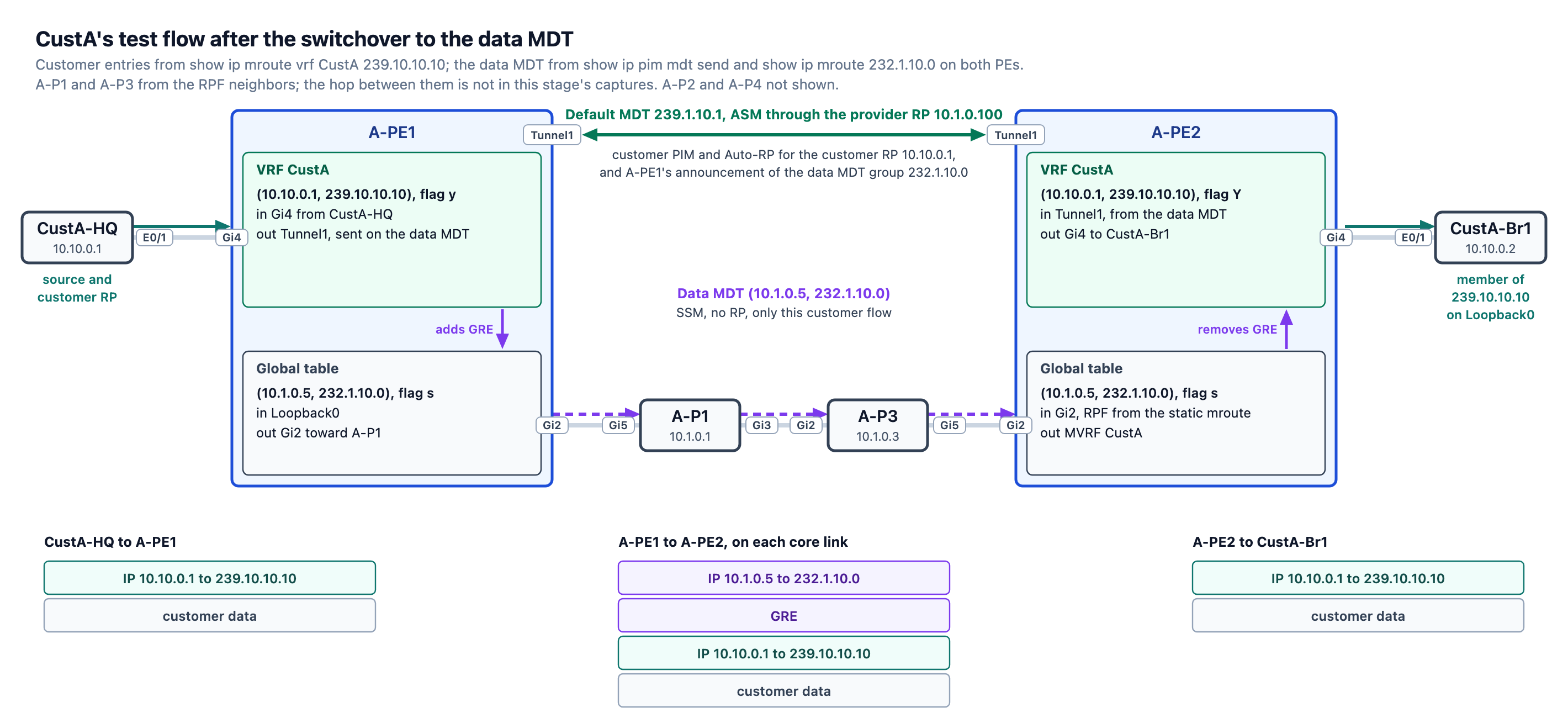
On A-PE1, show ip mroute vrf CustA 239.10.10.10 shows the flow with the y flag, Sending to MDT-data group:
(*, 239.10.10.10), 2d07h/00:02:35, RP 10.10.0.1, flags: S
  Incoming interface: GigabitEthernet4, RPF nbr 10.1.10.2
  Outgoing interface list:
    Tunnel1, Forward/Sparse, 00:00:54/00:02:35

(10.10.0.1, 239.10.10.10), 00:01:41/00:01:18, flags: Ty
  Incoming interface: GigabitEthernet4, RPF nbr 10.1.10.2
  Outgoing interface list:
    Tunnel1, Forward/Sparse, 00:00:54/00:02:47
show ip pim mdt send names the data MDT group, the first group of the pool:
A-PE1#show ip pim mdt send

MDT-data send list for VRF: CustA
  (source, group)                     MDT-data group/num   ref_count
  (10.10.0.1, 239.10.10.10)           232.1.10.0           1
232.1.10.0 is in 232.0.0.0/8, which ip pim ssm default in the previous post made the SSM range. Routers build only (S,G) trees for that range, with no RP. On A-PE1, show ip mroute 232.1.10.0:
(10.1.0.5, 232.1.10.0), 00:01:07/00:03:21, flags: sT
  Incoming interface: Loopback0, RPF nbr 0.0.0.0
  Outgoing interface list:
    GigabitEthernet2, Forward/Sparse, 00:01:07/00:03:21
s is the SSM Group flag. A-PE1 announces the new group over the default MDT, and A-PE2, which has a receiver, joins it. On A-PE2, show ip mroute vrf CustA 239.10.10.10:
(*, 239.10.10.10), 2d07h/00:02:59, RP 10.10.0.1, flags: S
  Incoming interface: Tunnel1, RPF nbr 10.1.0.5
  Outgoing interface list:
    GigabitEthernet4, Forward/Sparse, 00:00:29/00:02:59

(10.10.0.1, 239.10.10.10), 00:00:52/00:02:07, flags: TY
  Incoming interface: Tunnel1, RPF nbr 10.1.0.5, MDT:[10.1.0.5,232.1.10.0]/00:02:35
  Outgoing interface list:
    GigabitEthernet4, Forward/Sparse, 00:00:29/00:02:59
Y means Joined MDT-data group, and the incoming interface names the data MDT, [10.1.0.5,232.1.10.0]. A-PE2’s global entry for 232.1.10.0 has Mroute as well, because the same static mroute for 10.1.0.5 serves both MDT groups:
(10.1.0.5, 232.1.10.0), 00:03:18/00:02:15, flags: sTIZ
  Incoming interface: GigabitEthernet2, RPF nbr 10.1.1.29, Mroute
  Outgoing interface list:
    MVRF CustA, Forward/Sparse, 00:00:44/00:02:15
What’s Next
This post closes the second part of the lab. The next post starts the third part, on SP-B, with Flex-Algo.


Leave a Reply