An SR-TE policy sends traffic from a headend router along a list of segments to an end-point. A policy is identified by a “colour” and an end-point, and it can have several candidate paths: the valid one with the highest preference is active. BGP carries the colour on a route as an extended community, and a route whose colour and next hop match a policy is steered into that policy. With on-demand next-hop (ODN), the headend has one template per colour, and a route with that colour makes the headend create a policy to the route’s next hop.
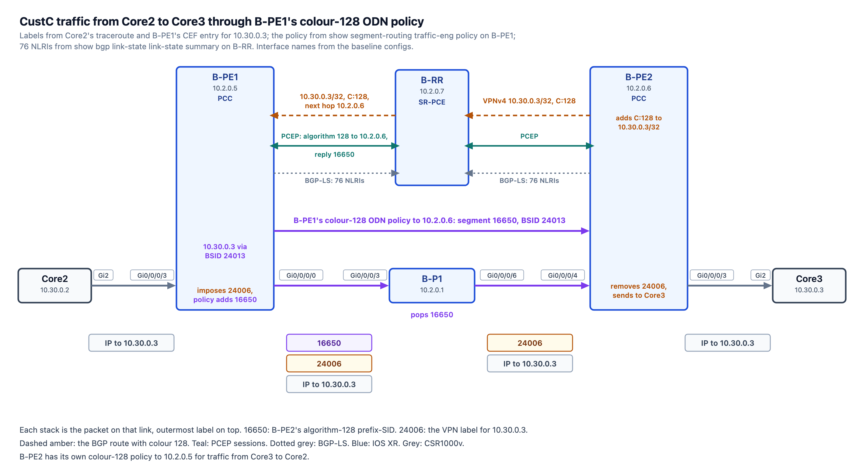
The previous post defined algorithm 128 on B-P1, B-PE1, and B-PE2 (the Flex-Algo post). CustC’s traffic between Core2 and Core3 still took the algorithm-0 path, via B-P2 and B-P3. In this stage, both PEs mark CustC’s routes with colour 128, and each PE has an ODN template that builds colour-128 paths from algorithm-128 prefix-SIDs. B-RR computes these paths. At the end of the lab, Core2’s traceroute to Core3’s loopback will look as below:
CustC-Core2#traceroute 10.30.0.3 source lo0 probe 1
Type escape sequence to abort.
Tracing the route to 10.30.0.3
VRF info: (vrf in name/id, vrf out name/id)
  1  *
  2 10.2.1.21 [MPLS: Labels 16650/24006 Exp 0] 5 msec
  3 10.2.1.50 [MPLS: Label 24006 Exp 0] 6 msec
  4 10.2.12.6 7 msec
Topology file: topology.clab.yml · Addressing: ipam.md · Stage configs, 3 nodes (B-PE1, B-PE2, B-RR): stage_configs/lab03-s2-spb-srte/
CustC’s L3VPN
CustC’s L3VPN on SP-B was built in the L3VPN post: VRF CustC on B-PE1 and B-PE2 with the route target 64502:30, and eBGP to Core2 and Core3. B-PE1’s VRF CustC routing table:
RP/0/RP0/CPU0:B-PE1#show ip route vrf CustC
Thu Jul  9 16:59:13.532 UTC

Codes: C - connected, S - static, R - RIP, B - BGP, (>) - Diversion path
       D - EIGRP, EX - EIGRP external, O - OSPF, IA - OSPF inter area
       N1 - OSPF NSSA external type 1, N2 - OSPF NSSA external type 2
       E1 - OSPF external type 1, E2 - OSPF external type 2, E - EGP
       i - ISIS, L1 - IS-IS level-1, L2 - IS-IS level-2
       ia - IS-IS inter area, su - IS-IS summary null, * - candidate default
       U - per-user static route, o - ODR, L - local, G  - DAGR, l - LISP
       A - access/subscriber, a - Application route
       M - mobile route, r - RPL, t - Traffic Engineering, (!) - FRR Backup path

Gateway of last resort is not set

C    10.2.12.0/30 is directly connected, 2w5d, GigabitEthernet0/0/0/3
L    10.2.12.1/32 is directly connected, 2w5d, GigabitEthernet0/0/0/3
B    10.30.0.2/32 [20/0] via 10.2.12.2, 2w5d
B    10.30.0.3/32 [200/0] via 10.2.0.6 (nexthop in vrf default), 00:06:57
Core2’s loopback, 10.30.0.2, is learned over eBGP from Core2, 10.2.12.2. Core3’s loopback, 10.30.0.3, is learned over iBGP with next hop 10.2.0.6, B-PE2.
Colour 128 on CustC’s Routes
B-PE1 and B-PE2 have the same configuration below:
extcommunity-set opaque FLEX128
 128
end-set
!
route-policy SET_COLOR_128
  if extcommunity rt matches-any (64502:30) then
    set extcommunity color FLEX128
  endif
  pass
end-policy
!
router bgp 64502
 neighbor 10.2.0.7
  address-family vpnv4 unicast
   route-policy SET_COLOR_128 out
  !
  address-family vpnv6 unicast
   route-policy SET_COLOR_128 out
  !
 !
!
The full files are B-PE1.ios and B-PE2.ios.
The route-policy finds CustC’s VPNv4 and VPNv6 routes by their route target, 64502:30, and adds colour 128 to them when the PE sends them to B-RR. The other routes go to B-RR unchanged. On B-PE1, Core3’s route arrives from B-RR with next hop 10.2.0.6 (B-PE2) and colour 128, shown as C:128:
RP/0/RP0/CPU0:B-PE1#show bgp vpnv4 unicast
Thu Jul  9 16:57:21.148 UTC
BGP router identifier 10.2.0.5, local AS number 64502
BGP generic scan interval 60 secs
Non-stop routing is enabled
BGP table state: Active
Table ID: 0x0
BGP main routing table version 32
BGP NSR Initial initsync version 1 (Reached)
BGP NSR/ISSU Sync-Group versions 0/0
BGP scan interval 60 secs

Status codes: s suppressed, d damped, h history, * valid, > best
              i - internal, r RIB-failure, S stale, N Nexthop-discard
Origin codes: i - IGP, e - EGP, ? - incomplete
   Network            Next Hop            Metric LocPrf Weight Path
Route Distinguisher: 10.2.0.5:10 (default for vrf CustA)
*> 10.2.10.0/30       0.0.0.0                  0         32768 ?
*> 10.10.0.3/32       10.2.10.2                2         32768 ?
Route Distinguisher: 10.2.0.5:30 (default for vrf CustC)
*> 10.30.0.2/32       10.2.12.2                0             0 64530 i
*>i10.30.0.3/32       10.2.0.6 C:128           0    100      0 64530 i
Route Distinguisher: 10.2.0.6:30
*>i10.30.0.3/32       10.2.0.6 C:128           0    100      0 64530 i

Processed 5 prefixes, 5 paths
By applying this policy, we’re marking specific prefixes, so the traffic to them can be steered based on this attribute.
The SR-TE Configuration
Below is the SR-TE configuration from B-PE1. B-PE2 has a similar configuration, with its explicit policy pointing to B-PE1:
RP/0/RP0/CPU0:B-PE1#show run segment-routing
Thu Jul  9 17:20:00.872 UTC
segment-routing
 global-block 16000 16999
 traffic-eng
  segment-list SL_ALGO128_PE2
   index 10 mpls label 16650
  !
  on-demand color 128
   dynamic
    pcep
    !
    metric
     type igp
    !
   !
   constraints
    segments
     sid-algorithm 128
    !
   !
  !
  policy EXPL_TO_PE2
   color 200 end-point ipv4 10.2.0.6
   candidate-paths
    preference 200
     explicit segment-list SL_ALGO128_PE2
     !
    !
   !
  !
  pcc
   source-address ipv4 10.2.0.5
   pce address ipv4 10.2.0.7
   !
  !
 !
!
The on-demand color 128 template applies to BGP routes that carry colour 128. When a route with colour 128 arrives, B-PE1 builds a policy from the template to that route’s next hop and steers the route into it. dynamic means the path is computed, and pcep means B-RR (PCE) computes it. metric type igp asks for the path with the lowest IGP metric, and sid-algorithm 128, under constraints and segments, allows only algorithm-128 prefix-SIDs.
The pcc block points B-PE1 to B-RR at 10.2.0.7 and uses B-PE1’s Loopback0, 10.2.0.5, as the source address. The segment list and policy EXPL_TO_PE2 are an explicit policy, covered at the end of the post.
B-RR as the SR-PCE
A path computation element (PCE) acts as a controller: it computes paths and tells the headend routers, the path computation clients (PCCs), where to steer the traffic. The PCE and the PCCs talk over the Path Computation Element Communication Protocol (PCEP). PCEP runs over TCP, on port 4189: a PCC sends a path request with the end-point and the constraints, and the PCE replies with the path, which in segment routing is a list of segments. In SP-B, B-RR was the most suitable router for the SR-PCE role, since it already has BGP sessions to both PEs. Its Loopback0 address, 10.2.0.7, is configured as the PCE address. B-RR learns the topology over BGP link-state (BGP-LS) from B-PE1 and B-PE2, so its BGP configuration has to have the link-state address family applied to both related neighbors:
pce
 address ipv4 10.2.0.7
!

router bgp 64502
 address-family link-state link-state
 !
 neighbor 10.2.0.5
  address-family link-state link-state
  !
 !
 neighbor 10.2.0.6
  address-family link-state link-state
  !
 !
!
On each PE, distribute link-state under IS-IS exports the IS-IS database, and BGP sends it to B-RR in the link-state address family of the existing session:
router isis 1
 distribute link-state
!
router bgp 64502
 address-family link-state link-state
 !
 neighbor 10.2.0.7
  address-family link-state link-state
  !
 !
!
Both PEs hold the same IS-IS Level-2 database, and B-RR receives 76 link-state NLRIs from each:
RP/0/RP0/CPU0:B-RR#show bgp link-state link-state summary
Thu Jul  9 16:53:24.514 UTC
BGP router identifier 10.2.0.7, local AS number 64502
BGP generic scan interval 60 secs
Non-stop routing is enabled
BGP table state: Active
Table ID: 0x0   RD version: 77
BGP main routing table version 77
BGP NSR Initial initsync version 1 (Reached)
BGP NSR/ISSU Sync-Group versions 0/0
BGP scan interval 60 secs

BGP is operating in STANDALONE mode.


Process       RcvTblVer   bRIB/RIB   LabelVer  ImportVer  SendTblVer  StandbyVer
Speaker              77         77         77         77          77           0

Neighbor        Spk    AS MsgRcvd MsgSent   TblVer  InQ OutQ  Up/Down  St/PfxRcd
10.2.0.5          0 64502   33993   33962       77    0    0 00:04:55         76
10.2.0.6          0 64502   33982   33966       77    0    0 00:01:09         76
B-RR’s 76 NLRIs are of three types: node, link, and prefix. Each of the eight routers has one node NLRI. Each router advertises each of its links twice, once in the IPv4 topology and once in the IPv6 topology, and SP-B’s 13 links have a router at each end: 13 × 2 × 2 = 52 link NLRIs. advertise passive-only keeps only Loopback0 in IS-IS, so each router has two prefix NLRIs, one IPv4 and one IPv6: 16 in total. 8 + 52 + 16 = 76.
The PCE topology built from that feed has eight nodes, SP-B’s eight routers, including the CSR1000v routers that do not take part in algorithm 128:
RP/0/RP0/CPU0:B-RR#show pce ipv4 topology summary
Thu Jul  9 16:52:52.394 UTC

PCE's topology database summary:
--------------------------------

Topology nodes:                8
Prefixes:                      8
Prefix SIDs:
  Total:                      11
  Regular:                     8
  Strict:                      0
Links:
  Total:                      26
  EPE:                         0
Adjacency SIDs:
  Total:                      52
  Unprotected:                26
  Protected:                  26
  EPE:                         0
show pce ipv4 topology counts the IPv4 topology only: 26 links and 8 prefixes. Of the 11 prefix SIDs, 8 are the algorithm-0 SIDs of the eight routers, shown as regular, and 3 are the algorithm-128 SIDs of B-P1, B-PE1, and B-PE2.
The ODN Policy, Colour 128
Here is how B-PE1’s policy entry looks after B-PE1 created the colour-128 policy from the template. It can be displayed with show segment-routing traffic-eng policy:
Color: 128, End-point: 10.2.0.6
  Name: srte_c_128_ep_10.2.0.6
  Status:
    Admin: up  Operational: up for 00:04:15 (since Jul  9 16:52:16.718)
  Candidate-paths:
    Preference: 200 (BGP ODN) (inactive) (shutdown)
      Requested BSID: dynamic
      Constraints:
        Prefix-SID Algorithm: 128
        Protection Type: protected-preferred
        Maximum SID Depth: 10
      Dynamic (inactive)
        Metric Type: IGP,   Path Accumulated Metric: 0
    Preference: 100 (BGP ODN) (active)
      Requested BSID: dynamic
      PCC info:
        Symbolic name: bgp_c_128_ep_10.2.0.6_discr_100
        PLSP-ID: 1
      Constraints:
        Prefix-SID Algorithm: 128
        Protection Type: protected-preferred
        Maximum SID Depth: 10
      Dynamic (pce 10.2.0.7) (valid)
        Metric Type: NONE,   Path Accumulated Metric: 0
          16650 [Prefix-SID, 10.2.0.6]
  Attributes:
    Binding SID: 24013
The ODN template creates two candidate paths: preference 200, computed by B-PE1 itself, and preference 100, computed by the PCE. With pcep configured, B-PE1 does not compute a path of its own, so preference 200 is shut down and preference 100 is the active path. A Binding SID (BSID) is a local label that the headend binds to a policy.
B-RR’s entry for B-PE1’s preference-100 path, from show pce lsp detail:
RP/0/RP0/CPU0:B-RR#show pce lsp detail
! Output trimmed to B-PE1's policy
PCC 10.2.0.5:

Tunnel Name: bgp_c_128_ep_10.2.0.6_discr_100
Color: 128
Interface Name: srte_c_128_ep_10.2.0.6
 LSPs:
  LSP[0]:
   source 10.2.0.5, destination 10.2.0.6, tunnel ID 2, LSP ID 2
   State: Admin up, Operation up
   Setup type: Segment Routing
   Preference: 100
   Prefix-SID algorithm: 128 (set: 1)
   PCEP information:
     PLSP-ID 0x1, flags: D:1 S:0 R:0 A:1 O:1 C:0
   Computed path: (Local PCE)
      SID[0]: Node, Label 16650, Address 10.2.0.6
D:1 is the PCEP delegate flag: B-PE1 has handed control of the path to B-RR. B-PE1’s request carries the end-point, 10.2.0.6, and the template’s constraint, Prefix-SID algorithm: 128. With that constraint, B-RR uses only the three routers that take part in algorithm 128, so the only path from B-PE1 to B-PE2 goes through B-P1. Every router on that path forwards B-PE2’s algorithm-128 prefix-SID, 16650, along its algorithm-128 shortest path to B-PE2, so B-RR’s computed path is one segment, 16650.
CustC’s Traffic in the Policy
B-PE1’s CEF entry for Core3’s loopback in VRF CustC:
RP/0/RP0/CPU0:B-PE1#show cef vrf CustC 10.30.0.3
Thu Jul  9 17:14:56.571 UTC
10.30.0.3/32, version 20, internal 0x5000001 0x30 (ptr 0xe70a4d0) [1], 0x600 (0xdb79728), 0xa08 (0xf69da08)
 Updated Jul  9 16:52:16.745
 Prefix Len 32, traffic index 0, precedence n/a, priority 3
  gateway array (0xd9e2d60) reference count 1, flags 0x38, source rib (7), 0 backups
                [2 type 1 flags 0x8441 (0xf6dc3a8) ext 0x0 (0x0)]
  LW-LDI[type=1, refc=1, ptr=0xdb79728, sh-ldi=0xf6dc3a8]
  gateway array update type-time 1 Jul  9 16:52:16.746
 LDI Update time Jul  9 16:52:16.747
 LW-LDI-TS Jul  9 16:52:16.747
   via local-label 24013, 5 dependencies, recursive [flags 0x6000]
    path-idx 0 NHID 0x0 [0xdd55610 0x0]
    recursion-via-label
    next hop VRF - 'default', table - 0xe0000000
    next hop via 24013/0/21
     next hop srte_c_128_e labels imposed {ImplNull 24006}

    Load distribution: 0 (refcount 2)

    Hash  OK  Interface                 Address
    0     Y   recursive                 24013/0
The route’s colour, 128, and next hop, 10.2.0.6, match the policy, so the route recurses on the policy’s BSID, local label 24013. B-PE1 imposes VPN label 24006, and the policy pushes 16650 as the outer label: the two labels B-P1 shows in the first traceroute.
IPv6 and the Reverse Direction
B-PE1’s CEF entry for Core3’s IPv6 loopback recurses on the same BSID, with VPN label 24007:
RP/0/RP0/CPU0:B-PE1#show cef vrf CustC ipv6 2001:db8:30::3
Thu Jul  9 17:29:24.102 UTC
2001:db8:30::3/128, version 17, internal 0x5000001 0x30 (ptr 0xf5dc658) [1], 0x600 (0xe3d71d0), 0xa08 (0xf69d228)
 Updated Jul  9 16:52:16.738
 Prefix Len 128, traffic index 0, precedence n/a, priority 3
  gateway array (0xe244280) reference count 1, flags 0x38, source rib (7), 0 backups
                [2 type 1 flags 0x8441 (0xf6dc648) ext 0x0 (0x0)]
  LW-LDI[type=1, refc=1, ptr=0xe3d71d0, sh-ldi=0xf6dc648]
  gateway array update type-time 1 Jul  9 16:52:16.739
 LDI Update time Jul  9 16:52:16.739
 LW-LDI-TS Jul  9 16:52:16.739
   via local-label 24013, 5 dependencies, recursive [flags 0x6000]
    path-idx 0 NHID 0x0 [0xdd55610 0x0]
    recursion-via-label
    next hop VRF - 'default', table - 0xe0000000
    next hop via 24013/0/21
     next hop srte_c_128_e labels imposed {ImplNull 24007}
    Load distribution: 0 (refcount 2)
    Hash  OK  Interface                 Address
    0     Y   recursive                 24013/0
One policy, to the IPv4 end-point 10.2.0.6, carries CustC’s IPv4 and IPv6 traffic. In Core2’s IPv6 traceroute, 2001:DB8:2:15::1 is B-P1 and 2001:DB8:2:1C::2 is B-PE2:
CustC-Core2#traceroute ipv6 2001:db8:30::3 source lo0
Type escape sequence to abort.
Tracing the route to 2001:DB8:30::3

  1 2001:DB8:2:24::1 25 msec 4 msec 1 msec
  2 2001:DB8:2:15::1 [MPLS: Labels 16650/24007 Exp 0] 18 msec 12 msec 4 msec
  3 2001:DB8:2:1C::2 [MPLS: Label 24007 Exp 0] 37 msec 7 msec 4 msec
  4 2001:DB8:2:25::2 5 msec 8 msec 5 msec
Core3’s traceroute to Core2 crosses B-P1, 10.2.1.49, with 16550, B-PE1’s algorithm-128 prefix-SID, on top of VPN label 24008:
CustC-Core3#traceroute 10.30.0.2 source lo0
Type escape sequence to abort.
Tracing the route to 10.30.0.2
VRF info: (vrf in name/id, vrf out name/id)
  1 10.2.12.5 3 msec 2 msec 2 msec
  2 10.2.1.49 [MPLS: Labels 16550/24008 Exp 0] 7 msec 11 msec 5 msec
  3 10.2.1.22 [MPLS: Label 24008 Exp 0] 8 msec 4 msec 4 msec
  4 10.2.12.2 3 msec *  3 msec
An Explicit Policy, Colour 200
B-PE1’s SR-TE configuration also has an explicit policy, written by hand: EXPL_TO_PE2, identified by colour 200 and end-point 10.2.0.6. Its candidate path uses SL_ALGO128_PE2, a list of labels in the order of their index, with one label, 16650, the same label B-RR computed for the ODN policy:
RP/0/RP0/CPU0:B-PE1#show segment-routing traffic-eng policy color 200
Thu Jul  9 16:55:03.753 UTC

SR-TE policy database
---------------------

Color: 200, End-point: 10.2.0.6
  Name: srte_c_200_ep_10.2.0.6
  Status:
    Admin: up  Operational: up for 00:07:07 (since Jul  9 16:47:56.689)
  Candidate-paths:
    Preference: 200 (configuration) (active)
      Name: EXPL_TO_PE2
      Requested BSID: dynamic
      Constraints:
        Protection Type: protected-preferred
        Maximum SID Depth: 10
      Explicit: segment-list SL_ALGO128_PE2 (valid)
        Weight: 1, Metric Type: TE
          16650 [Prefix-SID, 10.2.0.6]
  Attributes:
    Binding SID: 24011
No BGP route on B-PE1 carries colour 200, so no traffic uses this policy at this stage.
What’s Next
The next post connects CustC’s third site, Core1 behind A-PE2 in SP-A, to Core2 and Core3 with Inter-AS Option A between A-ASBR and B-ASBR.


Leave a Reply